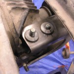
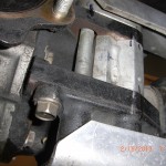
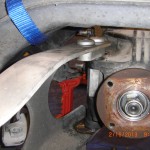
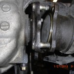
Remoivng miata donor parts 8 of 9, only 2 bolts left

Since last post I gave a thought , that maybe the next step should be to  remove the engine from the sub-frame, but decide I may need this mass to resist torque of removing ball joint castle nuts. It turns out this was the right decision.

First use a 17mm socket, which seems to be the go to socket for the suspension, and remove the lower bolt retaining the strut spring unit to the lower control arm. Repeat for the other side and put the strut spring units in the e-bay pile.

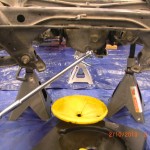
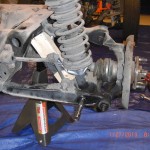
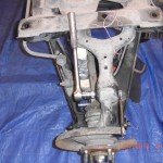
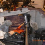
Next up I did remove the wheels to access the ball joint and tie rod  cotter keyed castle retaining nuts. You need to support the weight of the engine unit with the wheels off. Use jack stands or suitable support. As you know I do have the engine crane in position with the legs under the sub-frame. I place a couple of pieces of 2×4 material on the top surface of the engine crane and used the legs of the engine crane for supports, worked.But it may be possible to break loose the castle nuts with the wheels on, if so do so. First remove the 6 cotter pins from upper and lower control arms and the two tie rod ball joints. Use 17 mm socket to break loose the tie rod and the upper ball joint castle nut, not need to completely remove.

brake loose upper castle nut

brake loose tie rod castle nut


You will need a 21 mm socket to remove the lower ball joint retaining nut.

brake loose lower castle nut

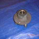
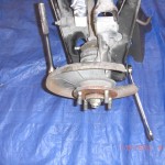
After the castle nuts are loosened go ahead and remove the wheels and tires if you have not done so by now. Slide brake rotors free of hubs, and use the 29 mm or the more common 1-1/8″ socket to remove the hut retaining nut(which we have previously loosened). After the nut is completely removed the hub is now free and and be removed from the stub axle see page 9:21 in the manual. Repeat for other side and place brake disk along with calipers, hubs and retaining bolts and nuts in the required donor pile parts.

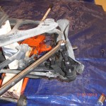
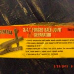
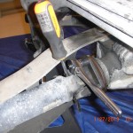
Now we need to separate two tie rod ball joints and 2 upper and 2 lower control arm ball joints. Refer to 8:16 in the manual. As you read the manual you will find out they were not able to purchase a separator tool that would fit. They use a wedge chisel separator and big hammer and brute force. My ball joints were very, very tight and I would not encourage anyone to remove the joint is this manner. I was able to buy an inexpensive 3/4″ ball joint separator tool for about $20.00 from Harbor freight. Their tool item number for this separator is 99849. You need this tool. It fit perfectly and made what could be a very tough job almost easy as I was able to separate all the joints and remove uprights in about 2 hours and that includes my time to make notes for this blog.

You NEED this tool!

I did one side at the time. I started by removing the steering rack tie rod ball joint first. A couple of suggestions for using this tool I loosed all the castle nuts until they were about flush with the head of the threaded part of the tie rod. You will soon find out when the tie rod breaks free of the Morse taper that it can be rather explosive and I thought it a very good safety idea to leave the castle nut in place to contain this separation.Also as  hint use some WD40.After tie rod is separated, remove castle nut completely and release tie rod from upright.

separating a tie rod ball joint

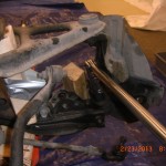
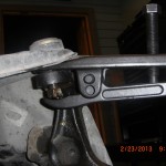
To left is the separator tool in position with the castle nut in place to contain separating parts.Make sure tool is in proper position, It is OK to tap  the forked end into place with a hammer to get proper insertion.
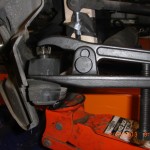
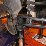
separator in positon on top joint

For the larger lower  joint you will need to adjust the separator tool to use the upper ( you want to increase the spread) pivot pin holes locations.You can see the different pin position in pictures.

Some suggestions on use of tool. I did apply WD 40 to taper joint area prior to positioning of tool on the ball joint. You will use your ratchet or breaker bar to turn the screw on the separator tool.

After several turns and the breaker bar is providing quite a bit of resistance to turn screw, this is when you are thinking to yourself, I can not believe it has not broke loose or something is going to break, Well this is the time to get a good heavy hammer and give the ball joint a swat with the hammer. Using this method two of my joints immediately separated. For the other I would tighten the screw anther half turn , then give it a few swats and then another ½ turn and with the next hammer blow it separated. Only one of my joint separated without using the hammer technique.

It always is amazing to me just how much retention force a morse style taper can provide with out any bolt applying pressure.  Many of the lower HP aviation engines attach the prop flange to the crank with a similar taper. I once needed 20 tons of force to remove a prop flange!. So it was expecting it would and should take some force to separate the joints from the upright.
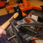
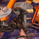
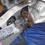
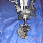
So after all your joints are broke loose, completely remove all the castel nuts and remove the upper ball joint first from the upright and then lower, the upright is now free.

lift upright free of ball joints

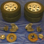
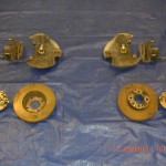
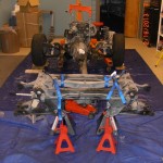
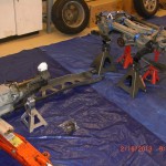
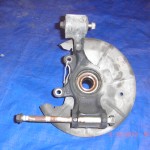
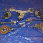
Put the upright in the required donor pile parts and repeat for the other side.Here is a group portrait of the front end donor parts including the wheels.


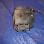
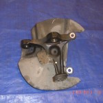
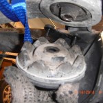
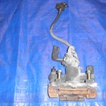
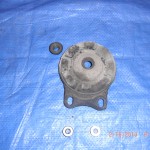
Below are a couple of  pics of the donor parts before recondioning. Hopefully they clean up an be VortX worthy.

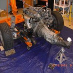
Well this concludes todays post. Basically all we have left to dissasemble is to remove the engine from the subframe motor mounts. Just 2 bolts left.

Stay tuned.
Front end donor parts, wheels

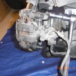
front caliper before pic

front upright with brake dust cover


front end donor part group


Removing miata donor parts 7 of 9, removing the PPF car now in split in half

Before moving to the front calipers as I mentioned on my last post. I decide first to disconnect the rear prop flange from the rear differential flange. Refer to page 4:2 in the manual. Use a 14 mm socket and 3/8″ drive socket and moving in a diagonal sequence first loosen and then remove the 4 retaining nuts and bolts.Bag and label fasteners and put into the donor pile.Slide the drive shaft slightly forward to clear differential flange. Since I have yet to drain my fluids at this time I did not remove the prop-shaft, I simply tied up with twin for the moment and moved to the front calipers, but now would be a good time to drain fluids and shaft.

drive shaft rear bolts

Remove 4 rear drive shaft to differential flange bolts

flange bolts removed and prop-shaft slid forward

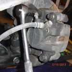
As I left off on the last post I next removed the front brake calipers and rotors(temporarily). Refer to pages 9:10 in the manual for instruction. Use a 14 mm socket to remove the 2 caliper to upright mounting bolts.

Removing front caliper bolts

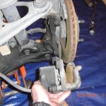
After you have caliper removed repeat for other side and put the calipers and mounting bolts into the required donor pile of parts.The brake disk is now free and and can be lifted off of the hub and removed. You will need to do this in order to set up your dial indicator and check the front hub bearings for play. I did not bother to check the any of the brake disk for run out as I intend to use performance slotted disk all around, but if you are re-using the disk now would be a good time to check the disk for run-out. Refer to manual page 9:10 for instruction on run out check.

front caliper

Remove caliper

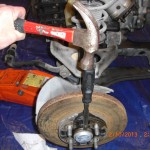
Refer to page 9:21 in manual. I needed to use a wood chisel to help separate the rather tight front hub dust covers. I position the sharp edge of the  chisel at the seam( looking for the widest part) and tap chisel with hammer and moving in a circular pattern continue the tapping until you have created a small gap. Then you can use a pry bar or more blunt end screw driver and hammer to further separate the dust cover. Then you can grab with channel lock style pliers and remove completely.

Seperate dust cover

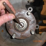
Straighten the hub nut locking stake

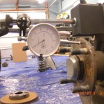
Next in similar fashion to what I did at the rear, I set up my dial indicator to check for lateral play of the front hub bearing. Max allowable play is .002, Mine was less than .001, so they are usable. Reset the dial indicator and repeat check for other hub.

check front hub

Dial indicator set up to check front hub wheel bearings


After this wheel bearing check. I prepare to loosen the hub retaining nut and used a drift punch to straighten the hub nut stakes prior to loosening hub retaining bolts this is the same procedure we already did for the rear. Using 1 1/8″ socket with breaker and pipe extension for leverage and the 2×6 SST in place to prevent the hub from rotating I  used my weight as I stood on the pipe and broke the 159 Ft lb tight hub nut loose.

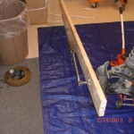
SST in position ready to loosen hub nut

I should note I did clamp a pair of channel locks onto the steering rack shaft as the wheels wanted to turn when torqued.Repeat loosening procedure for other side, but do not remove hub nut and hubs at this time, I just want to break loose while I have the engine weight and PPF in place.At this time I replaced the brake disk and replaced both front wheels and tires to allow a stable platform to support engine weight while I return my attention to removal of rear differential.

As we are now ready to remove the rear differential I drained all the fluids. Use  a 24 mm socket for the rear differential and the transmission drain plug and 19 mm socket for the engine drain plug.

draining diff oil

Draining the differential oil

I did use some cheesecloth as a screen to train the tranny oil into just to see if there are any big pieces of metal that should not be in the oil. There were none, good. Which makes me ask, is there an aftermarket source for magnetic miata drain plugs, may be a good idea to use one. Next I decide to remove the PPF, In doing so the front sub-frame and transmission and rear sub-frame with diff and control arms still attached will need to be able to support themselves independently.So in preparation of PPF removal I support the rear sub-frame with 4 jack stands. I support the transmission with a single jack stand and the front sub-frame is supported by the wheels and tire which we put back on. For safety , I did wrap a couple of strap tie downs around the diff just to make sure it would not hit the floor if it slip off the jack during removal. As it turned out this was not necessary,but why not.

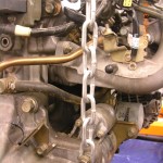
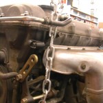
An issue I had was where to attach the chains to pull the engine. The manual says to use the factory engine removal hoops to attach the chains to. Well my car does not have factory engine removal hoops. On the drivers side at the front of the head near the valve cover part line is what looks to be where the hoop is located in the manual is a bolt hole that may work, but diagonally on the passenger side rear there is not counterpart. I do see some potential holes but all the potential suspects on the head do not seem substantial enough to me and I am reluctant to use for fear of cracking the head. So after looking around, I decide to partially remove the upper most starter bolt and attach a chain here for the passenger side rear , and at drivers side front I attached chain to the old and now unused but very strong AC compressor bolt. See pics. But the concern I do have about these location is not the strength but whether the C of G of these locations is high enough to prevent a rotation during lift. It may not be ideal but I believe I am good. We will find out soon if these are good hoist attach points.

hoist location

I used starter bolt as a chain host location

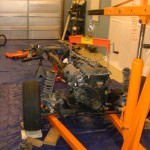
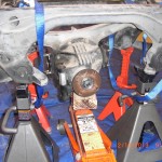
I attach the chains properly using by load leveler and position the engine crane in position and apply a very slight preloaded to chains just to make sure all is secure. So now I have the rear sub supported by 4 stands, the front sub-frame supported by wheels and engine hoist and tranny by jack stand and a floor jack in position below the rear differential


.

engine crane in position

chain hoist location

AC bolt being used for engine hoist location


So now we are ready to proceed and should have all our supports in position to finish the harvest. Next I break loose and loosen the rear differential carrier mountings. I want to loosen these carrier bolts while the differential is still attached to the PPF so we can use the weight of the PPF to torque against to loosen the carrier mounts. For reference page 4:27   11.0 .

Use 12 mm socket to loosen two nuts and 17 mm socket to loosen larger center mounting bolt that is torqued to 62 to 72 ft lb. Just loosen for now. Repeat for opposite side carrier mount. We will remove carrier mounts  after we have removed the PPF.

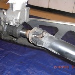
Since all fluids are drained  and there will not be any oil to be spilled. I now removed the prop-shaft from the transmission tail-housing . Just slide the pro-shaft rearward and it almost removes itself. Some builder have the prop-shaft shortened to suit the VortX. The factory Miata does not have serviceable U joints. I will be using a custom length drive-shaft with serviceable U joints. These custom drive-shaft will be available from Fastcraft motorsport for approx. $249.00 and you have a shaft that can be rebuilt.So for me the prop-shaft is for the e-bay pile. But some builders do use it and this is a viable idea if you have a local shop that can shorten the donor shaft.

slide propshaft to rear to remove


driveshaft

Removed propshaft


Refer to page 4:3 in the manual for PPF removal instruction.

First remove the support bracket between the transmission tail casting and the PPF. Usa a 17 mm socket to remove bolt holding bracket to PPF and 14 mm socket to remove 2 bolts holding bracket to transmission . I am not sure at this time if this bracket is required for the VortX so I bagged up this bracket and hardware and placed in the “maybe pile of parts”

trans bracket

Reomve the PPF to transmission mounting bracket

PPF to tailhousing bracket

At the front of the PPF two long bolts attach transmission to PPF. Use  17 mm socket to remove these bolts.

.

Top view pic .Witness marks per manual.These collars are not removed to remove the PPF. view of differential spacer. This is used for the VortX

After both bolts are removed you need to remove the “collar” located at the bottom of the PPF at the front bolt location. This collar passes through the PPF and the inner part inserts into the differential mount casting.There is a ready made relief in the rear of this collar to insert a pry-bar. Use some WD40 to assist. I had a pry-bar the exact size needed and was easy to start, but do not pry too hard as you will only jam it as you pull form one side. After I got it started I grabbed in by hand and tapped it with a hammer and it easily removed. This must be removed. Once removed we are read to remove the PDF and split the car in half so to speak.

use prybar to remove collar.

We are now ready to remove the PPF as it is free. At the rear it can be move sideways until clear of the differential casing. Some wiggling and some WD40 may be helpful here, once free of the rear differential casing you can easily pull the PPF rearward to remove from the transmission casing.The PPF is surprisingly light, seems to weigh less than 20 LBS.

Rear PPF

Sliding PPF off differential casing


The donor is now split in half and we are ready to remove the rear diff now supported independently by 4 jack stands. First position the floor jack under the differential to assist removal.

SPLITTSVILLE


Refer back to manual page 4:27  11. Now that the PPF is removed from the differential  we are ready to completely remove the the differential carrier mountings. Use 12 mm socket to remove the two carrier mounting bolts and 17 mm socket to to remove the center bolt. Repeat for other side.

Removing differentiall carrier mounting

differential carrier mount


The differential is now free and can be lowered with the floor jack to ground.

jack in position ready to lower diff

I like this picture as it is all that is left of the original donor and the disassembly will be the subject of our next post.


Rear doner parts
grouping of rear drivetrain donor parts required for the VortX

This is a group portrait of the rear drive-line donor parts


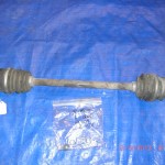
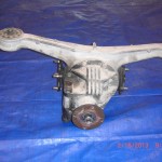
Some “before” pics of donor parts to be used  to compare with after refurbishment.

Rear brake caliper

Rear brake caliper before refurbishment

Rear upright, with hub and backing disk backing plate

halfshaft


rear diff

Close up of differential and spacer unit


Well that completes this post and I can see the finish line of the deconstruction process, after-all there is not much left.


Removing miata donor parts 6 of 9, deconstructing the miata continues

I was not too pleased with my last post regarding grouping the pictures toward the end of the post and will return to mixing the pictures within the commentary. Besides deconstructing the Miata, I am using these pages to prepare for writing the VortX miata assembly blog. So just bear with me as I experiment with this forum.

Now that the wiring harness is removed, we can finish removing the remaining donor parts, which is most of the drive-train all still connected to the PPF and front and rear sub-frames..With the body removed I have excellent access and this should make the rest of this deconstruction process go rather smoothly.

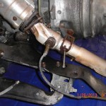
Since the down pipe still attached appears to be lower than the PPF and may possible contact the ground when the differential is removed from the PPF,I decide now would be a good time to remove the down pipe with the O2 sensor still attached to get it out of the way.Use a 12 mm socket to remove exhaust clamp bolt. Use 14 mm socket to remove down-pipe to exhaust header nuts.The nut closest to the block is difficult to remove, you will need to use a U-Joint swivel with 3 inch extension and with this set up I was able to remove, see pic,I would loosen this nut first. I intend to Turbo my VortX build and will need a custom down pipe. For those of you building a normally aspirated engine I would put this in the maybe required pile of parts. I will clarify if needed in a later post.

Using U joint swivel and extension to reach

You will need a U joint swivel and short extension to reach this bolt

Downpipe loose ready to remove

Down pipe with O2 sensor ready for removal

Next I turned my attention to the rear. I should mention, make sure you have the rear sub-frame  securely supported on jack stands and the front wheels chocked to prevent rolling off the stands. With rear wheels removed I decide to remove both rear brake caliper assembles. Use 14 mm socket to remove two retaining bolts per caliper. But bolts and calipers into the donor pile.Slide off brake rotors put in donor pile.

Remove Rear Calipers.


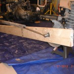
Now I decide the rear hubs, hub carriers(uprights) and CV axle drive shifts are my focus. To remove the rear hubs refer to page 9:21 in the manual. I first set up my magnetic  base and dial indicator to check wheel bearing play. Mine is about 1/10,000 so excellent.As I read instruction 20 on page 9:22 Then I realize I have one of those OOPS moments. I started this deconstruction process by asking myself ,”where do I start?”. Well I think I now have the answer to this question. I no longer have a hand brake or any hydraulic brake system to prevent the hubs and axles from turning when  the axle nut that is retained by 216 ft lb of torque is loosened. So if you are following along and have not removed your donor cars brakes, I would for a first step check your front and rear hub run-out per the manual and I would use the still operable brake system and break loose the the hub nuts, drive-shaft to differential and axle CV joint to differential bolts. Do not remove, just break them loose. But since I no longer have this option, I had to make my own Special Service Tool(SST) to remove the axle nuts and drive shaft bolts. This was done for the cost of a 2x6x8. I cut the 2×6 down to about 7 feet. Using a blue magic marker I applied the marker to the ends of the hub bolts and with one end of the 2×6 just behind the front tire I placed the opposite end of the  2×6 up to the still wet hub bolt ends to transfer the blue marker ink onto the 2×6.I drilled these holes with a drill bit, sorry I did not record the size but just pick one just slightly larger than the hub bolts. Now  I  applied the blue marker to the end of the threads where the hub nut is attached. I used a small 3/16″ drill bit to drill a pilot hole into the center of this larger blue mark.  I then used a 2″ hole saw and using the pilot hole as my guide I sawed from both sides of the 2×6 to center to remove the round wood waste. I now would recommend a slightly larger 2 1/8″ hole saw if available but the 2″ got the job done. So what I am going to do is place the drilled holes over the wheel hub bolts to make a long lever to press against the floor as I loosed the hub nuts. To remove the drivers side hub nut , I place one end of the 2×6 is just behind front tire. This will prevent rotation to left as we loosen. I am able to use the large 2 inch center hole to access the hub bolt with the socket.  Now with this SST in position I am ready to proceed following the instructions on page 9-22 in the manual to remove hub. But at this time before removing the hub nut, and with the SST in position  take some time and break lose the nuts retaining the inner CV joints to differential connection joint for both axles. Use a 14 mm wrench or 14 mm 3/8″ drive socket as 1/2″ drive will not fit to break loose these bolts. Then using a 14mm 3/8″ drive socket brake loose and if you want you  can remove the 4 bolts retaining the rear drive shaft yoke to the differential mounting flange. We really do not need to mark drive-shaft position to differential as we will be using a custom or modified shaft. The reasoning you  want to do loosen the axle bolts prior to removing both rear Hubs as after you have the  hubs removed, you will not be able to use the 2×6 SST to prevent rotation of axles. OK now we can proceed to remove hubs and axles.
I did not have a 29 mm socket which is the correct size to remove the hub nuts, so I followed the advice in the manual and used a 1 1/8″  socket size and it fit perfectly. Before you attempt to loosen the hub nut make sure you use a drift punch to straighten out the locking staked portion of the nut. It is on tight enough without forgetting to this step.

break loose rear hub bolts

SST used to retain hub rotation.

Release staking

Using a drift to release hub nut staking

With 1 1/8″ socket over nut and using my 1/2″ breaker bar with about a 3ft extension of black pipe positioned to gain leverage, I placed one foot on the SST and pushed down on the breaker bar until it broke loose. Actually it broke loose  rather easily. So after doing it this way using the 2×6 as a SST, this method is actually not a bad alternative. Next I used a 14 mm socket to remove the single bolt that connects the sping/damper unit to the lower control arm.

remove lower rear strut bolt.

Repeat to other side and place the spring units into the e-bay pile.Use a 14 mm socket and 14 mm wrench remove upper upright bolt.

remove upper control arm bolt

Use a  17 mm socket & 21 mm wrench or socket and remove the long lower upright pivot bolt.

removing rear upright

remove lower upright bolt

Apply some WD 40 to aid removal of this long bolt. Now we are ready to remove the unrestrained upright hub unit from the axle splines. One side of my Donner  the hub unit  separated from the splines with no effort at all, for the other side I followed the advice of the manual by placing the hub nut over the axle and tapping with hammer and pulling

upright removed

Rear hub removed

simultaneously after a couple of rather easy taps the hub came free from the splines. Remove upright and place upright and bolts in the required donor pile. Repeat for other side. I did mark the location of the axle shafts to the differential mounting flange as manual suggest. Using 14 mm socket remove the all ready loosed axle bolts , remove axle,label and put into the donor pile. Repeat for other side to remove axle.We  now

inner rear axle

inner rear axle nuts removed

have both rear calipers and mount assemblies, 2rear brake rotors, 2 rear uprights and hub assemblies, 2 rear CV joint half shat axles and all associated hardware all labeled in the donor pile.And  the down pipe with O2 sensor in the “maybe pile”.

I next intended to go ahead and remove the rear differential as this is the last major donor part that is connected to the rear sub-frame.But I decide it may be  best at this time and a good idea while the car is securely supported at rear by the rear sub-frame( as the ppf is directly connected to the differential) to remove the front calipers, rotors and to break loose the front hub nuts as we can use the mass of the engine to work against to help remove the tightly torqued hub nuts.