Rebuilding Miata front calipers

Begin rebuild of calipers

We now move on to rebuilding the brake calipers. See before donor pics.

Donor Caliper before

In retrospect I did not do this process in the best order. This is also the first time I used the product Evapo-Rust rust remover.

Evapo-Rust is a chemical method to remove rust and I was not sure what to expect, nor was I certain that the product may not cause harm to the caliper piston bores. So this is why I decided to just leave the Caliper pistons with seals in the caliper and submerge the fully assembled calipers into the evapo-rust product. I purchase a 5 gal can of evapo-rust from Northern Tool. But this amount is more than you need. I used plastic  food container just large enough to completely submerge the front and rear brake calipers into. I did one at a time.

soaking in Evaporust

soaking in Evaporust


I put the first front caliper into the solution and I was concerned that possible my evapo-rust was expired! I did buy it about 4 months ago, I do not know what I was expecting but I was expecting to see some sort of chemical reaction as I looked into the container,  but nothing looked like it was happening. My plan was to do 1 caliper a day, so I could let soak 24 hours before removal. So that is what I did. The next day I removed the caliper and I was still not impressed, but per instructions you are to spray with clean water after removal, so I hosed off the caliper and using a tooth brush I scrubbed the caliper while in a clean bucket of water. The result is well like magic. The calipers now look like new, at least on the outside! The cleaned parts upon removal from solution have a slight black film residue, I believe this is do to the rust conversion process and once you wash this off this film  the metal underneath looks amazing.

Magic of chemical rust removal

more magic

I am now sold on this product and will recommend it’s use. I also cleaned the pins and hardware, and machined surfaces look like new with no signs of chemical etching, so I believe this product would be perfectly safe if I had used evapo-rust to clean the hubs or front axles as opposed to media cleaning. The instruction also say after chemical cleaning the parts will not begin to flash rust for several days, so you have some time before you will have to paint or primer. This is a benefit of time you do not have when doing media cleaning in cabinet. See after pics. I used the same solution and container to clean all 4 rotors and I did allow each caliper to soak for 24 hours. I started on Sunday as I have plans to leave Friday and would be out of town for a week, So I decided I should just go ahead and primer the calipers with high temp KBS primer

high temp primer

Thursday before I leave and finish the rebuilding them  when I return. But of course if I remove the pistons and find a caliper with pitting I am just wasted my time and some primer. So I masked off the parts I did not want painted and I used foam ear plugs to keep the paint out of the threads. This worked out really well.

See primed caliper pictures below.

ear plugs keep paint off threads

FRONT CALIPER PRIMED

Now begin the  disasemble and rebuid of calipers  so they are as good on the inside as they appear to look from the outside. If I were to do over would be my frst step would be to disasemble and verify calipers are satisfactory for rebuilding and then I would submerge the cleaned and disasembled caliper cores into the Evap0-Rust and remove clean with dawn and then clean again with brake clean.

I now begin the rebuild of the front calipers.

For the procedure I will refer you once again to the enthusiast work shop manual page 9:10 section 13 for the step by step instructions.

Here I will supplement the manual with pictures and some comments. Not much in tools are required air compressor to remove pistons a  5/16” line wrench and 12 mm socket. Use 12mm wrench to remove caliber bracket, and banjo bolt securing the flex line, we will not use the donor flex line as the VortX kit includes quality braided flex lines.

remove banjo nut to use air to remove piston

protect piston


Keep the banjo bolt and it is best to use new copper washer or heat the old and anneal. Next pic is removing the pistons from the caliber. I placed some wood material and an old wax pad to prevent any potential damage to piston during removal, you may be surprised.

extracted piston ready for hand removal

I used compressed air, I tried 20 Lb but needed about 35 to get the piston to start moving slowing then the all of a sudden it pops out and is restraint by my wood blocking. Make sure you keep your fingers out the way during this procedure.

using pick lift out the square piston seal


Remove and save the bleeder screw.

Inspect piston and caliper for rust and pitting. This could be the end game for your caliper if pitting exists. Next use a pick to help get the square piston seal from its groove. Next using a brake cleaner product thoroughly clean the piston and caliper and blow out the passages. I used a tooth brush to clean the piston seal and piston boot grooves in caliper. I used some 2000 wet paper to polish the piston. I also wrapped some the 2000 grit paper around my cylinder hone to polish the bore of the caliper, worked good.

polished bore with 2000 grit

used tooth brush to clean grooves

blow with compressed air


polishing piston with 2000

polished

I used Mazda OEM caliper rebuild kit part # NAY5-33-26Z this Mazda Kit is $45.00 and about half if you decide to use an aftermarket parts store kit. There may not be any disavantage to use an aftermarket caliper seal kit but I decided to go OEM as Miata brakes have an excellent reputation for durability and thought using the factory parts will maintain their performance.

new OEM caliper rebuild parts

lubricate replacement seals in DOT 4

lubricate cylinder bore with DOT 4

Of course after caliper and piston are polished once again clean with brake cleaner, don’t forget to clean the banjo bolt and bleeder screw.

I used a foam brush to lube the caliper bore and paint the piston with DOT 4 brake fluid. I used pentosin super Dot 4 brake fluid. I do not recommend using the DOT 5 Silicon. Before installation of piston and boot cover I dunk in a cup of brake fluid.

piston boot positioned to install in caliper

ready to install in caliper

Position the boot dust seal as shown onto piston. Then insert the piston into the caliper.  Be careful to make sure the piston is square to the caliper as you apply force to insert.

fully engage outer boot seal in groove

verify boots inner seal fully seated in piston groove

You will feel a bit of resistance as the piston skirt engages the square seal, but as long as you are square keep applying force , you will be able to tell when the piston is passed the seal as the piston will now more easily slide into the bore. Next make sure the boots outer seal is fully seated in its groove in the piston skirt. Now is a good time to verify the boots outer seal is fully seated in the caliper groove, if so now fully compress the piston into the caliper.

piston with new seals fully depressed in caliper

Install bleeder and banjo bolt with new copper washer and the caliper is now rebuilt. See pic. I do plan to paint but that is for another day after all four caliper are rebuilt. Now we need to replace the piston pin rubber guide in the caliper bracket.  I used a razor blade to cut rubber guide to help assist in removing it from the bracket. See pic.

almost out

used 3m cloth to polish bushing bores

I cleaned up both caliper bracket bores using some 3M polishing pad material, see pic.

I used some Permatex ultra disk brake caliper lube to lube the pin bushings for install. I will use the same grease to lubricate the caliper pins.

lube bushing with permatex ulta and used pin as install took


Finally I install the the remaing boot, I needed some assist using a clay modeling tool, see pic. These can be handy tools for this type of work; they do not have sharp edges that can slice a seal. I think I will leave this off the other caliper until after I paint them.

clay tools helpful with seal work

Now all that is left is to polish the pins with the 2000 grit and paint, not a bad job at all. I actually took longer to write this blog than to rebuild the calipers. So I recommend removing your pistons and inspecting for pitting and if all is well rebuild them and the money saved can be used in the build elsewhere.

Next we will rebuild the rears, which are a bit more involved.


Repacking Miata Front Hubs

Repacking Miata front hubs

Here we are disassembling and cleaning the front hubs in preparation to repack with grease.

The manual says the front hubs are not serviceable. This is partially true but I did learn on the Mazda racer spec Miata community forum that most all serious Mazda racers repack even brand new hubs as normal race prep. This forum   http://mazdaracers.com/forum/100-spec-miata/    is excellent to learn about these techniques and other Miata set up items.

As to whether we should do this will be a topic for discussion at a later date. But suffice I decided to do the hub repack as I wanted the experience of how to do this procedure.

My post here is only to supplement this very excellent article I believe was originally posted by Karl Zimmerman on the Mazda racers forum. Please click Repacking front Hubs for the full text of how this is done step by step. The photos and text are excellent.

As we noted during the parts Harvest my donor hubs had an almost nil amount of play and being quality NTN hubs I decide I will repack for use in the VortX. Grease is cheap. See pics of front and back donor hubs.

Front of NTM donor hub

Rear of donor NTM hub

rear of donor NTM hub


Label each hub for reassembly. Example DS for Drivers Side, I used A and B, put if doing again would rather classify as DS or PS (passenger

flat washers in position

flat washer in postion

side).  I recommend using the 4 washer method as in article. As you can see I had a fender washer at hand and cut in 4 pieces to do the same job. I did supplement the 4 washer method by placing another larger washer on top of the 4 individual washers; my thought was this will allow the socket a more level surface to press against for removal of race. It did not take much force to tap out the race.

20 mm socket in positon

Round up some baby food containers or prescription bottles or some type of suitable containers to keep the removed bearing races, holders and bearings separate. So you will have Hub PS  and separate container for Hub PS inner and Hub PS outer races, holder and bearings.  You will also have same for the DS hub. See pic of how I organized the parts.

all race& bearings are labeled

But before I repack the bearing I decide if I want to clean and repaint the hubs now is the time. The cleaning is a necessary step but the prep and paint is for cosmetic only.

It  is important not to get these parts mixed up or premature failure is almost certainly to result so be careful.

FYI you can use a 1 1/8″ in socket in place of 29mm as called out in instructions.


remove bearings from holder

Please click Repacking front Hubs for the full text of how on this proceedure. My pictures are only to supplement.The dissembled hubs are solvent cleaned in the parts washer and then washed in dawn dish soap, applied some WD40 to bearing surfaces to prevent any flash rust to machined races. I decided I would clean hubs exterior surface rust in the blast cabinet in preparation for paint.


home made hub seat kit


If I would do again I would use the chemical method I used to clean the calipers for rebuild. I will describe in the Caliper rebuild. As you can see I went to great lengths to prevent and media and later paint from entering hubs and getting on race surface. I used black electrical tape to cover the inner circumference edge of hub. I was as the home depot and I found some bathtub drain gaskets and round furniture sliders with Teflon face that I would use to make seals for the open ends of the hubs. Bought some 3/16” bolts nuts and washers to compress the gaskets and sliders against the hub ends, I even went so far as to use silicon applied to the washers to further seal out media. See pic.

the seal parts in order

hub sandwich


This actually only took a few minutes to prepare for use. as I only had to drill 3/16” holes in the center of the sliders and then screw together with the hubs as the middle of this sandwich. It did work great. See pics of hub sandwich. I media cleaned, air blasted and then washed the hub sandwich in dawn soap to prepare for paint.

media cleaned on left

Preped ready to repack

I painted the Hubs with KBS silver rustseal coating. While I had the spray equipment out I also painted the spindles and brake covers with Bill Hirsh aluminum engine enamel. Bill Hirsh offers several quality paints at www.hirschauto.com As you remember I had previously primed the spindles. The KBS rustseal coating I used for the hubs is applied to the bare unprimed media cleaned surface as no primer is recommended for rust prevention. If the parts are to see direct sunlight this KBS rustseal coating will need top colored top coat. but the hubs are not in sunlight and besides hubs are maintenance items anyway. I then applied to all painted parts KBS diamond finish clear coat. This needs to be applied within 45 minutes of top coat or you will have to do additional surface prep so plan your paint work in advance to save time. After the paint was dry I removed the bolt and the Teflon surface made separating the sliders easy. I wish I could take credit and say I planned it that way, but actually I was going to use plain wood when I saw the sliders for sale on the way to the check out counter and they were the correct diameter  and  did not require any effort for me to cut any wood to size. So now we have cleaned, blasted and, painted hubs.

painted and looking good

I also learned from the Spec Miata forum that Red line Synthetic grease is the most recommended go to grease for this job. I thought I would have to wait and order this grease but after going to redline web site I found out there is a redline distributor only 1 mile from my shop I did not know about! Most hub packers re-use the old seals but I purchased new seals. These are not available from Mazda, but  Dave Wheeler of Advanced autosports  www.advanced-autosports.com has went to the effort to have replacement hub seals manufactured for the hubs and are available at Dave’s website for racers to purchase. Dave has also authored a book I recommend title the Spec Miata Constructors Manual and is worth the read. I did not damage my seals during removal and could have reused, but decided to use seals the new seals.


Hub, cleaned parts ready to pack

Here is one hub. I have allready cleaned the hub races thoroughly with WD40 and also all bearings, inner races and holder are cleaned and put in labeled sanitary container ready to be repacked.

So with Red line grease in hand and my new seals and the above file on display on my computer screen it is time to get on with the repack.

I start by repacking the hub’s rear race first. This is the easy side to do. I applied Red Line synthetic grease to holder and installed the ball bearings. Pay attention to how the bearings fit into the holder. Notice you are pushing them in from the outside or downward as you are viewing from above. If you try it put bearings in center of circle and then try pushing from the center of the circle to outside of the circle they will not go into place and too much force may break the holder. Make note of this as this technique

will come in handy when you install the front side holder and bearing.

Next I applied a liberal amount of grease to the inner hub race and then dropped the holder with bearings into the bed of grease.   I applied some grease to outer inner race and with aid of socket I tapped into position see pic. Then clean up the extra grease and take picture.

grease applied to rear race


apply some grease to rear race

Tapping race into position

So far so easy. Now we turn the hub over to repack the front race. This is a bit more difficult. First I applied some grease to holder and work into position. This is the scary part as if you break the holder you can only get the holder when you buy a new hub! I found holding the holder about 60 degree angle from horizontal worked best for me. You will have to compress the holder slightly to get into position. You may not want to do this in cold temperature, not sure but winter temp may affect the pliability of holder. Once the holder is in place it is time for our next dexterity test. It was so easy to install the bearings when they are on the work bench; I thought this would go fast too. It took me a few times to find the best technique. Like the article says, installing the bearings 180 to each other in sequence does help. But the trick is to hold the retainer in position with the index finger of one hand and push the bearing with the index finger of the other hand, Like you are trying to hold the bearing between the tips of your pointed index fingers, remember the bearing go into place from above easy when we did the holder on the bench, Same here. Once this is done you are home free. After bearings are in place apply a liberal amount of grease and coat the front inner race with grease and tap into position.

front holder in place

Next tap in the front inner race and all I have left to do is to install the inner seal. See pics for orientation.


Orientation of grease seal

Just start the seal square , I was able to push on by hand and then used a socket and lightly tapped to verify fully seated. I was able to repack the other hub in half the time. Overall repacking the hubs is nothing to be afraid of . If your donor has quality hubs with play within spec, why not repack and reuse?  On the other hand if your donor has low quality hubs and you plan to take to take your VortX to the track you may as well just bite the bullet and buy new hubs now.

Looks like the front brakes are missing,

So the next post will be rebuilding the Calipers.

Before and after pics here.

degreased spindles

VortX Ready


Refurbishing Miata front axle parts

Starting at the front.

I am going to refurbish the donor parts starting from the front axle and working toward the rear axle. I start with refurbishing the front end parts, the spindles, hubs, and brakes. All other front end parts furnished in the VortX kit are new! Actually if you want you could just install the parts as removed from the Miata provided they were in good working order, but I do want a pleasing and sanitary car so I will spend some extra time and effort and some of the budget in this area to clean, coat the parts and rebuild the calipers.

I start by removing the dust covers from the front spindles, us a 12 mm socket to remove the 3 dust cover bolts. Next stop is trip to the parts washer. Which in itself is worthy of some comment.

remove dust shield

What to use for solvent? I did a lot of searching around. The solvent cleaner must be aluminum safe. The leaves out such readily available cleaners like purple power and such. In fact most all cleaners are caustic to aluminum it seems. I purchased Crown PSC 1000 in a 5 gal can. You can usually walk into a Tractor supply pay them $41.99 and take it home so there is not any shipping expense. Besides the price the reason I selected it is this solvent is this product is a medium aliphatic Naphtha solvent and is a recommended solvent by Boeing aircraft to use in degreasing of aluminum and is not caustic to aluminum. It is flammable and should be used in ventilated flame free area and of course wear gloves when using. I located my parts washer on an enclosed patio next to my shop. So this works out great for me.

cleaning in washer

Since I bought the Red Devil and on occasion I rent a 2 seat Symphony 160 on occasion to fly, I investigated what I could use to clean these bare alcad aluminum airplanes. I found something I should already have known about. This is Extreme Simple green. This is not the same simple green you buy in Wal-Mart. In fact you will probably have to order it and have shipped. I found prices on Amazon for as low as $79.00 including shipping for 5 gal pail. You can buy from www.skygeek.com. It is made to clean aluminum.

degreased spindles

cleaned

This product is water based so it is not flammable. But the big plus for this product is that it meets Boeing spec D6-17487 and Pratt Whitney spec PWA3609. So it is safe for all metals! Degreases and offers corrosion protection too, does not harm paint, plastics, coatings, low odor, can be used in parts washers without need for heating. Sounds like great stuff. I have not tried it yet but I plan to order some soon.  The same material is also marketed as motor sports cleaner and is sold in some race shops. You can put this in a bucket with water and wash your monocoque aluminum chassis and painted body and just hose it off. So this is just a FYI about an alternative cleaner you can use in your parts washer or to wash your car or airplane. I’ll update when I give it a try.


media cleaning dust covers


blasted ready for primer


Back to task at hand. After cleaning spindles in the parts washers I wanted to prepare for paint. I washed the parts with dawn dish soap. I have a bead blast cabinet and wanted to use it to remove all surface oxidation. The medium I am using is glass purchased from www.tptools.com. I wanted to make sure I do not damage any machined surface. So I had an idea, hmmm. How bout if I paint all the machined surfaces with plastic coat? You can buy this stuff at any craft store. My nephew uses this stuff to stencil race numbers on his car for track days, does not harm to the paint and peels off easily and this is a common practice, so this is where the idea comes from. So I give it a try and coated the spindle surface with the plastic coats. See pic. Next spindles are bead blasted.

media cleaned on left

grinding off cast flash

Looking good but I notice some casting flashing that could be a stress riser. So I get out the dremel and grinding stone and do a bit of clean up smoothing our any crevices. For this process it does not hurt to use a little extra caution to protect the spindle, in case of a slip of hand and dremel. The cardboard tubes from empty paper towel rolls came in handy. See cleaned up pic. If I was building a “show car” the process would be to spend many, many hours to remove metal to such an extent to have a smooth almost polish surface. My goal is to use the Miata parts with minimal cosmetic time and effort. In fact this step is not necessary, but since the VortX RT suspension is more visible I decided to clean up the bigger gobs of casing flash since it is now or never.

used plastic coat to protect machined surfaces

plastic coat applied

Of course immediately after clean media blast you want to apply coating. Prior to paint I used more corks to prevent paint from getting into the tie rod and upper and lower ball joint holes. I painted using my old faithful and very low cost Rust 0leum heavy rusted metal primer. I will top coat.

spindles ready for paint

Since I primed these parts I have become aware of a product called RustSeal made by KBS coatings. Can be applied direct to blasted parts. I used this product to repaint the aluminum heel scuff guards on the floorboards of the airplane. This is some tough paint. Other paints always have worn off quickly. I tested this paint and it is fuel proof. Only issue is KBS web site says the color is not stable in sunlight and would need a top coat when exposed to direct sun, but  this coating is extremly chip and excellent as rust prevention. So this is probably a tougher more chip resistant primer than the Rust Oleum. But not inexpensive at about $15.00 a half pint. All we need to do now is finish paint the spindles and brake dust covers. I will top coat later along with the cleaned and repacked front hubs. Which is a good place to start the next post.


Prepping for degreasing

remove ignition harness


We recently finished the disassembly and this post begins the next phase which is to refurbish the donor parts for the build. The first step is to clean the parts and I start by preparing the engine for degreasing. I thought best to remove the all electrics from the engine so I can degrease. Unfortunately I am writing this 5 months after I did this work using my notes I took at the time, and some of the details are a bit lacking. My resolution is to write this blog within 48 hours any procedure which is about the length of my memory these days. With the engine sitting on the mobile stand I made we have 100% complete access. I uncharacteristically just jumped right in and did not read the manual in advance, Now would be a good time to take several picture of the assembled engine including all the fuel injection harness, alternator, remaining electrics, hoses etc to reference for reassembly.  I wish I took a few more. You always think at the time you will never forget where this hose or that connector goes, famous last words. I am consulting the manual as write the blog to give some reference to my disassembly.  I started by removing the fuel rail. Use a 12 mm socket to remove the 3 securing bolts and collars which will come loose when bolts are withdrawn. I was not able to remove rail until I used 10 mm socket to temporarily remove solenoid bracket to allow removal of rail. I thought I could remove the rail with injectors and harness as a complete assembly.

12 mm to remove bolts

removing fuel rail bolts

fuel rail now free

This plan was not working out well and I would have known that if I reviewed the manual 5:20 P 19:  Per the manual, remove PCV hose from cam cover (obvious) and disconnect any hoses that are in the way. Next you will need to release the main electrical connector of the fuel injection rail harness. The harness is also attached to the rail with cable ties, cut the ties. Next you will need to remove the individual injector electrical connectors.

harness disconected remove injectors

Use a small screwdriver to apply pressure (but not too much, use care) to push the locking release tab. Now you can remove the rail harness. I labeled the connectors and removed the injection rail harness. Remove rail and pull to release injectors. Of course all these parts are labeled and put in donor pile for safe keeping. Review the pics.

Next I turned my attention to the coil pack. Refer to 5:27, P 27B in manual. Use a 12 mm socket to remove 3 coil support bracket retaining bolts.  Remove coil and ignition wires, put in donor pile.

remove coil bracket


Next up remove alternator, remove the adjustment strap inner bolt and the adjuster bolt you need to remove the pivot bolt,.


OOPS

Then I have an OOPS moment. The engine stand 2×2 angle did not allow the removal of pivot bolt. So I had to remove the angle to free the alternator. Next I removed the exhaust header shield. Use 10 mm socket to remove 7 bolts and 3 nuts.

So If you are reading ahead, remove the alternator prior, if you are using this low buck angle engine dolly.

remove heat shield


I put the shield in the maybe pile. Next remove the AC compressor mounting bracket from block. Use 14 mm socket to remove 4 bolts and use 12 mm socket to remove 1 long bolt from front. Put this very Heavy bracket in the scrap pile where it belongs.

remove AC bracket


AC bracket front bolt removal


We are almost ready to degrease. So I went to the craft store and bought an assortment of corks and plugged any and all openings we would not want to get wet.

seal opening from debris, water

I moved the engine and diff outside for degreasing. Used Engine solvent and several stiff brushes and with the aid of the power washer and repeated the process for areas that needed additional cleaning , now the engine and differential are looking good enough to transplant, but I believe they will be in for some additional surgery before they are VortX ready, but it is always nice have clean sanitary parts to work with.


degreaing diff


Next we continue refurbisment. I want my car to have a good clean appearance and will be conditioning the parts, painting and detailing as such. But I should note that I do not have any attention to make a show car from my kit. I  will be using my VortX as a track day car so it will be seeing hard use and no need for elaborate paint and finish, but still want an VorX RT with asthetic appeal and my goal is to do the parts prep at reasonable expense. That is what is to follow.


Removing miata donor parts 9 of 9, engine removed & we make an engine dolly

It is too long since last post. I really need to make it a rule to write the post within 48 hours of doing the job task. This is easier for my memory.

My nephew was in town from TX and 48 hours turned into a couple of weeks. So here goes. At my last post we only had to remove the engine from the sub frame or should I say the sub frame from the engine. So that is what I did next.

Use a 14 mm socket with short extension to reach the engine mount retaining bolt through the recessed round bulkhead access located on the underside of the front sub-frame. See pic.

Remove mount nuts

Repeat for other engine mount. Remove nut and large flat washer. See pic.

Remove prior to engine removal

After bolts are free I used the engine crane and lifted the engine free of the front sub-frame. I little wiggling of the sub frame was needed to assist. This engine mount is broken, See pic.

This mount was broken

The rubber part should have stayed with the fabricated bracket still attached to the engine. I have ordered MazdaSpeed competition engine mounts for the VortX build. I am creating a growing list of list of all the Mazda and aftermarket part numbers used in refurbishing and building the VortX, I will publish this list for builder’s reference.

See pic of metal brackets that the new MazdaSpeed Competition will cradle.

ENGINE MTG BRACKETS PUT IN DONOR PARTS

Put these metal brackets and hardware in the donor parts pile. This was bout a 10 minute or less job.

With the engine suspended above the front sub-frame,

front and rear subframes

UP, UP and AWAY

I picked up the sub-frame and moved it out of the way. But now what am I going to do with the heavy engine? I really did not give this enough for forethought and I do want to be able to move this around the shop.  After looking the engine over I noticed a pair of vertical holes you will find them if you look behind alternator and just below and in front of oil filter and similarly on the opposite side of the block. This gave me an idea for a very simple and cheap way to support and move the engine around the shop. I found some rusty 2x2x1/8 angle in my garden shed and a piece of 2×4 wood framing I will use to make an engine support. I cut the angle stock into two pieces 10-1/2” long. I then drilled two holes in one angle face     ( where I will bolt to the engine block) I located the top hole 1 1/8” (STD steel gage) from the back of 90 degree bend and the same 1 1/8” from the end of the 10-1/2” angle. I then located the second hole 1 -13/16” below the first hole location. I drilled the holes using a 7/16” drill. These two holes will bolt the angle to the engine block.

Now using the same 1 1/8” gage I drilled a 3/8” diameter hole 1 ¼” up from the other end of the 2 and ½”angle and on the opposite face of angle. This hole will bolt to the 26 inch 2×4 with 5/16” x 2” bolts. Cut the 2×4 to a length of 26 inches.

Make another angle to be a mirror image of the first.

HOLE LOACATIONS, Note: 45 deg notch on angle to right

I trial fit the angles to the block and I had to cut a 45 degree corner off of one angle face to clear the oil filter. See pics of the rusty angles with drilled holes. I decided I would paint the angles prior to use so I will finish this support frame tomorrow. So at this time I used a 14mm socket to remove the bolts that retain the steering rack to the sub-frame. This is not a necessary step and if you want you can leave attached to the front sub-frame, but since I am waiting for paint to dry, now is a good time to remove the rack. The VortX comes with a brand new quick ratio rack, so I am only removing the donor car rack to put in the e-bay for sale pile.

I painted the rusty angles with Rust-oleum rusty metal primer, this is my favorite paint for any ferrous metal refurbishment projects and I would like to make some commentary about this primer.

I have used this primer for years and I am most impressed on how it prevents return of rust. I first used this primer many years ago to paint a pipe used for a mail box support. My only preparation was to wire brush the major rust scaling off. I did not fully remove the existing rust and painted over the remaining rust with Rust-oleum rusty metal primer, I did not bother to put a top coat on. I fully expected it to return to the fully rusted condition in very short time. Long story short, this pipe looked as good as the day I painted it several years later! I have since used it many times and always with the same outstanding results, it really does the job of preventing return of rust. So for this reason I intend to use this paint as my go to primer for any parts that I recondition by stripping, bead blast etc. prior to finish painting.

For example I intend to paint the uprights and the differential and front and rear hubs. The differential and hubs will be subjected to some moderated but not high temps. Will this paint hold up? So I decided I would do an experiment to find out. I used a 3 inch piece of the same angle used for the engine stand and painted one side of the angle with this primer and the other side with VHT engine enamel. I put the piece in the oven at a temp I estimate the max for these parts of 200 Deg F for several hours. Both test samples held up great. So I kept turning up the heat and after 12 hours at 450 Degrees F, I removed the samples and using a primitive and unscientific test of a scraping a knife along the painted surfaces, the Rustoleum sample held fast and surprisingly the VHT paint was soft and some scraped off! So while I do not intent to use this primer for engine or brake calipers, I feel assured this is good primer paint for all but high heat applications. After the paint dries I was able to find 4 bolts from my coffee can of bolts I removed during disassembly to fit the holes in the engine block to mount my now nicely painted and dry angles to. After bolting these angles in place, see pic

BOLTING 2X4 TO ANGLES

Angle bolted to engine block, notch for oil filter

I clamped the 2×4 to the front face of the angles. I made sure the bottom of the 2×4 was about ½” below the angles so the angles would not scrap the floor surface. I marked the holes and drilled using a 3/8” drill. Then I bolted the drilled 2×4 to the face of the 2×2 angles using 5/16” bolts, see pic.

I then decided I wanted to keep the transmission off the floor and simply cut a piece of 2×4 to a length of approx 4-3/4” and positioned below the rear transmission mounting and marked and drilled ¼” pilot holes. Then using 2 ½’ x 3/8” hex headed wood screws I bolted the wood to the trans mount. Built as described the bottom of the 1.8L engines oil pan is about 1” above the floor surface. Adjust your angle lengths to suit if more clearance is desired.

SIMPLE REAR STAND ON DOLLY

Now that the engine trans unit is safely supported I still have the problem of moving it around the shop. My original plan was to buy some castors and attach directly to the stand I made, but then I read the Harbor freight flyer and seeing 1000 Lb capacity 11 ½ x17 ½ furniture movers on sale for about $10.00 each I had another and very simple plan.

I bought two of these and stopped at Lowe’s bought a precut 1” x 8”x48” piece of wood used for making stairway runners. I also picked up six 5/16” x 2” lag bolts. I simply drilled three 3/8” holes in each dolly and bolted the stair runner to it. Very simple and easy to make. I used the engine crane to lower engine onto this mobile “skateboard” platform. It works great and I can easily move around the shop and I am sure this “skate board” will find future use for other purposes. With the engine stand completed we have now concluded the deconstruction phase of this project and this will be the last post under the harvesting of donor parts topic heading, hence “last stand” post title.

FRONT VIEW ON SKATE BOARD

SIDE VIEW ON DOLLY

ON THE MOVE

I must admit I was not looking forward to the disassembly process. But it went much easier than I thought and I actually enjoyed it and this was an excellent way to learn  details about the Miata that will serve me during the build. I now have a good assortment of quality parts to sell that should allow me to recover most of the initial expense of the donor purchase. I invested a total of less than 40 hours in disassembling the donor and half as much writing the blog. In retrospect using the Miata as a single donor to build the VortX is to me is a “no brainer” and I highly recommend to potential builders to buy a Miata( go to Co-Part to find your donor Car) and do the disassembly yourself. You will learn a lot and this is a very cost effective way to go.

Now I must say I am very much looking forward to the next phase of this project.

What comes next? Well before we can get into the build I will first need to refurbish some of donor parts for the build. So the topic heading for my next post will be  Refurbishment of the donor parts. Will be posting soon.


Remoivng miata donor parts 8 of 9, only 2 bolts left

Since last post I gave a thought , that maybe the next step should be to  remove the engine from the sub-frame, but decide I may need this mass to resist torque of removing ball joint castle nuts. It turns out this was the right decision.

First use a 17mm socket, which seems to be the go to socket for the suspension, and remove the lower bolt retaining the strut spring unit to the lower control arm. Repeat for the other side and put the strut spring units in the e-bay pile.

Next up I did remove the wheels to access the ball joint and tie rod  cotter keyed castle retaining nuts. You need to support the weight of the engine unit with the wheels off. Use jack stands or suitable support. As you know I do have the engine crane in position with the legs under the sub-frame. I place a couple of pieces of 2×4 material on the top surface of the engine crane and used the legs of the engine crane for supports, worked.But it may be possible to break loose the castle nuts with the wheels on, if so do so. First remove the 6 cotter pins from upper and lower control arms and the two tie rod ball joints. Use 17 mm socket to break loose the tie rod and the upper ball joint castle nut, not need to completely remove.

brake loose upper castle nut

brake loose tie rod castle nut


You will need a 21 mm socket to remove the lower ball joint retaining nut.

brake loose lower castle nut

After the castle nuts are loosened go ahead and remove the wheels and tires if you have not done so by now. Slide brake rotors free of hubs, and use the 29 mm or the more common 1-1/8″ socket to remove the hut retaining nut(which we have previously loosened). After the nut is completely removed the hub is now free and and be removed from the stub axle see page 9:21 in the manual. Repeat for other side and place brake disk along with calipers, hubs and retaining bolts and nuts in the required donor pile parts.

Now we need to separate two tie rod ball joints and 2 upper and 2 lower control arm ball joints. Refer to 8:16 in the manual. As you read the manual you will find out they were not able to purchase a separator tool that would fit. They use a wedge chisel separator and big hammer and brute force. My ball joints were very, very tight and I would not encourage anyone to remove the joint is this manner. I was able to buy an inexpensive 3/4″ ball joint separator tool for about $20.00 from Harbor freight. Their tool item number for this separator is 99849. You need this tool. It fit perfectly and made what could be a very tough job almost easy as I was able to separate all the joints and remove uprights in about 2 hours and that includes my time to make notes for this blog.

You NEED this tool!

I did one side at the time. I started by removing the steering rack tie rod ball joint first. A couple of suggestions for using this tool I loosed all the castle nuts until they were about flush with the head of the threaded part of the tie rod. You will soon find out when the tie rod breaks free of the Morse taper that it can be rather explosive and I thought it a very good safety idea to leave the castle nut in place to contain this separation.Also as  hint use some WD40.After tie rod is separated, remove castle nut completely and release tie rod from upright.

separating a tie rod ball joint

To left is the separator tool in position with the castle nut in place to contain separating parts.Make sure tool is in proper position, It is OK to tap  the forked end into place with a hammer to get proper insertion.

separator in positon on top joint

For the larger lower  joint you will need to adjust the separator tool to use the upper ( you want to increase the spread) pivot pin holes locations.You can see the different pin position in pictures.

Some suggestions on use of tool. I did apply WD 40 to taper joint area prior to positioning of tool on the ball joint. You will use your ratchet or breaker bar to turn the screw on the separator tool.

After several turns and the breaker bar is providing quite a bit of resistance to turn screw, this is when you are thinking to yourself, I can not believe it has not broke loose or something is going to break, Well this is the time to get a good heavy hammer and give the ball joint a swat with the hammer. Using this method two of my joints immediately separated. For the other I would tighten the screw anther half turn , then give it a few swats and then another ½ turn and with the next hammer blow it separated. Only one of my joint separated without using the hammer technique.

It always is amazing to me just how much retention force a morse style taper can provide with out any bolt applying pressure.  Many of the lower HP aviation engines attach the prop flange to the crank with a similar taper. I once needed 20 tons of force to remove a prop flange!. So it was expecting it would and should take some force to separate the joints from the upright.

So after all your joints are broke loose, completely remove all the castel nuts and remove the upper ball joint first from the upright and then lower, the upright is now free.

lift upright free of ball joints

Put the upright in the required donor pile parts and repeat for the other side.Here is a group portrait of the front end donor parts including the wheels.


Below are a couple of  pics of the donor parts before recondioning. Hopefully they clean up an be VortX worthy.

Well this concludes todays post. Basically all we have left to dissasemble is to remove the engine from the subframe motor mounts. Just 2 bolts left.

Stay tuned.

Front end donor parts, wheels

front caliper before pic

front upright with brake dust cover


front end donor part group


Removing miata donor parts 7 of 9, removing the PPF car now in split in half

Before moving to the front calipers as I mentioned on my last post. I decide first to disconnect the rear prop flange from the rear differential flange. Refer to page 4:2 in the manual. Use a 14 mm socket and 3/8″ drive socket and moving in a diagonal sequence first loosen and then remove the 4 retaining nuts and bolts.Bag and label fasteners and put into the donor pile.Slide the drive shaft slightly forward to clear differential flange. Since I have yet to drain my fluids at this time I did not remove the prop-shaft, I simply tied up with twin for the moment and moved to the front calipers, but now would be a good time to drain fluids and shaft.

drive shaft rear bolts

Remove 4 rear drive shaft to differential flange bolts

flange bolts removed and prop-shaft slid forward

As I left off on the last post I next removed the front brake calipers and rotors(temporarily). Refer to pages 9:10 in the manual for instruction. Use a 14 mm socket to remove the 2 caliper to upright mounting bolts.

Removing front caliper bolts

After you have caliper removed repeat for other side and put the calipers and mounting bolts into the required donor pile of parts.The brake disk is now free and and can be lifted off of the hub and removed. You will need to do this in order to set up your dial indicator and check the front hub bearings for play. I did not bother to check the any of the brake disk for run out as I intend to use performance slotted disk all around, but if you are re-using the disk now would be a good time to check the disk for run-out. Refer to manual page 9:10 for instruction on run out check.

front caliper

Remove caliper

Refer to page 9:21 in manual. I needed to use a wood chisel to help separate the rather tight front hub dust covers. I position the sharp edge of the  chisel at the seam( looking for the widest part) and tap chisel with hammer and moving in a circular pattern continue the tapping until you have created a small gap. Then you can use a pry bar or more blunt end screw driver and hammer to further separate the dust cover. Then you can grab with channel lock style pliers and remove completely.

Seperate dust cover

Straighten the hub nut locking stake

Next in similar fashion to what I did at the rear, I set up my dial indicator to check for lateral play of the front hub bearing. Max allowable play is .002, Mine was less than .001, so they are usable. Reset the dial indicator and repeat check for other hub.

check front hub

Dial indicator set up to check front hub wheel bearings


After this wheel bearing check. I prepare to loosen the hub retaining nut and used a drift punch to straighten the hub nut stakes prior to loosening hub retaining bolts this is the same procedure we already did for the rear. Using 1 1/8″ socket with breaker and pipe extension for leverage and the 2×6 SST in place to prevent the hub from rotating I  used my weight as I stood on the pipe and broke the 159 Ft lb tight hub nut loose.

SST in position ready to loosen hub nut

I should note I did clamp a pair of channel locks onto the steering rack shaft as the wheels wanted to turn when torqued.Repeat loosening procedure for other side, but do not remove hub nut and hubs at this time, I just want to break loose while I have the engine weight and PPF in place.At this time I replaced the brake disk and replaced both front wheels and tires to allow a stable platform to support engine weight while I return my attention to removal of rear differential.

As we are now ready to remove the rear differential I drained all the fluids. Use  a 24 mm socket for the rear differential and the transmission drain plug and 19 mm socket for the engine drain plug.

draining diff oil

Draining the differential oil

I did use some cheesecloth as a screen to train the tranny oil into just to see if there are any big pieces of metal that should not be in the oil. There were none, good. Which makes me ask, is there an aftermarket source for magnetic miata drain plugs, may be a good idea to use one. Next I decide to remove the PPF, In doing so the front sub-frame and transmission and rear sub-frame with diff and control arms still attached will need to be able to support themselves independently.So in preparation of PPF removal I support the rear sub-frame with 4 jack stands. I support the transmission with a single jack stand and the front sub-frame is supported by the wheels and tire which we put back on. For safety , I did wrap a couple of strap tie downs around the diff just to make sure it would not hit the floor if it slip off the jack during removal. As it turned out this was not necessary,but why not.

An issue I had was where to attach the chains to pull the engine. The manual says to use the factory engine removal hoops to attach the chains to. Well my car does not have factory engine removal hoops. On the drivers side at the front of the head near the valve cover part line is what looks to be where the hoop is located in the manual is a bolt hole that may work, but diagonally on the passenger side rear there is not counterpart. I do see some potential holes but all the potential suspects on the head do not seem substantial enough to me and I am reluctant to use for fear of cracking the head. So after looking around, I decide to partially remove the upper most starter bolt and attach a chain here for the passenger side rear , and at drivers side front I attached chain to the old and now unused but very strong AC compressor bolt. See pics. But the concern I do have about these location is not the strength but whether the C of G of these locations is high enough to prevent a rotation during lift. It may not be ideal but I believe I am good. We will find out soon if these are good hoist attach points.

hoist location

I used starter bolt as a chain host location

I attach the chains properly using by load leveler and position the engine crane in position and apply a very slight preloaded to chains just to make sure all is secure. So now I have the rear sub supported by 4 stands, the front sub-frame supported by wheels and engine hoist and tranny by jack stand and a floor jack in position below the rear differential


.

engine crane in position

chain hoist location

AC bolt being used for engine hoist location


So now we are ready to proceed and should have all our supports in position to finish the harvest. Next I break loose and loosen the rear differential carrier mountings. I want to loosen these carrier bolts while the differential is still attached to the PPF so we can use the weight of the PPF to torque against to loosen the carrier mounts. For reference page 4:27   11.0 .

Use 12 mm socket to loosen two nuts and 17 mm socket to loosen larger center mounting bolt that is torqued to 62 to 72 ft lb. Just loosen for now. Repeat for opposite side carrier mount. We will remove carrier mounts  after we have removed the PPF.

Since all fluids are drained  and there will not be any oil to be spilled. I now removed the prop-shaft from the transmission tail-housing . Just slide the pro-shaft rearward and it almost removes itself. Some builder have the prop-shaft shortened to suit the VortX. The factory Miata does not have serviceable U joints. I will be using a custom length drive-shaft with serviceable U joints. These custom drive-shaft will be available from Fastcraft motorsport for approx. $249.00 and you have a shaft that can be rebuilt.So for me the prop-shaft is for the e-bay pile. But some builders do use it and this is a viable idea if you have a local shop that can shorten the donor shaft.

slide propshaft to rear to remove


driveshaft

Removed propshaft


Refer to page 4:3 in the manual for PPF removal instruction.

First remove the support bracket between the transmission tail casting and the PPF. Usa a 17 mm socket to remove bolt holding bracket to PPF and 14 mm socket to remove 2 bolts holding bracket to transmission . I am not sure at this time if this bracket is required for the VortX so I bagged up this bracket and hardware and placed in the “maybe pile of parts”

trans bracket

Reomve the PPF to transmission mounting bracket

PPF to tailhousing bracket

At the front of the PPF two long bolts attach transmission to PPF. Use  17 mm socket to remove these bolts.

.

Top view pic .Witness marks per manual.These collars are not removed to remove the PPF. view of differential spacer. This is used for the VortX

After both bolts are removed you need to remove the “collar” located at the bottom of the PPF at the front bolt location. This collar passes through the PPF and the inner part inserts into the differential mount casting.There is a ready made relief in the rear of this collar to insert a pry-bar. Use some WD40 to assist. I had a pry-bar the exact size needed and was easy to start, but do not pry too hard as you will only jam it as you pull form one side. After I got it started I grabbed in by hand and tapped it with a hammer and it easily removed. This must be removed. Once removed we are read to remove the PDF and split the car in half so to speak.

use prybar to remove collar.

We are now ready to remove the PPF as it is free. At the rear it can be move sideways until clear of the differential casing. Some wiggling and some WD40 may be helpful here, once free of the rear differential casing you can easily pull the PPF rearward to remove from the transmission casing.The PPF is surprisingly light, seems to weigh less than 20 LBS.

Rear PPF

Sliding PPF off differential casing


The donor is now split in half and we are ready to remove the rear diff now supported independently by 4 jack stands. First position the floor jack under the differential to assist removal.

SPLITTSVILLE


Refer back to manual page 4:27  11. Now that the PPF is removed from the differential  we are ready to completely remove the the differential carrier mountings. Use 12 mm socket to remove the two carrier mounting bolts and 17 mm socket to to remove the center bolt. Repeat for other side.

Removing differentiall carrier mounting

differential carrier mount


The differential is now free and can be lowered with the floor jack to ground.

jack in position ready to lower diff

I like this picture as it is all that is left of the original donor and the disassembly will be the subject of our next post.


Rear doner parts
grouping of rear drivetrain donor parts required for the VortX

This is a group portrait of the rear drive-line donor parts


Some “before” pics of donor parts to be used  to compare with after refurbishment.

Rear brake caliper

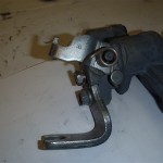
Rear brake caliper before refurbishment

Rear upright, with hub and backing disk backing plate

halfshaft


rear diff

Close up of differential and spacer unit


Well that completes this post and I can see the finish line of the deconstruction process, after-all there is not much left.


Removing miata donor parts 6 of 9, deconstructing the miata continues

I was not too pleased with my last post regarding grouping the pictures toward the end of the post and will return to mixing the pictures within the commentary. Besides deconstructing the Miata, I am using these pages to prepare for writing the VortX miata assembly blog. So just bear with me as I experiment with this forum.

Now that the wiring harness is removed, we can finish removing the remaining donor parts, which is most of the drive-train all still connected to the PPF and front and rear sub-frames..With the body removed I have excellent access and this should make the rest of this deconstruction process go rather smoothly.

Since the down pipe still attached appears to be lower than the PPF and may possible contact the ground when the differential is removed from the PPF,I decide now would be a good time to remove the down pipe with the O2 sensor still attached to get it out of the way.Use a 12 mm socket to remove exhaust clamp bolt. Use 14 mm socket to remove down-pipe to exhaust header nuts.The nut closest to the block is difficult to remove, you will need to use a U-Joint swivel with 3 inch extension and with this set up I was able to remove, see pic,I would loosen this nut first. I intend to Turbo my VortX build and will need a custom down pipe. For those of you building a normally aspirated engine I would put this in the maybe required pile of parts. I will clarify if needed in a later post.

Using U joint swivel and extension to reach

You will need a U joint swivel and short extension to reach this bolt

Downpipe loose ready to remove

Down pipe with O2 sensor ready for removal

Next I turned my attention to the rear. I should mention, make sure you have the rear sub-frame  securely supported on jack stands and the front wheels chocked to prevent rolling off the stands. With rear wheels removed I decide to remove both rear brake caliper assembles. Use 14 mm socket to remove two retaining bolts per caliper. But bolts and calipers into the donor pile.Slide off brake rotors put in donor pile.

Remove Rear Calipers.


Now I decide the rear hubs, hub carriers(uprights) and CV axle drive shifts are my focus. To remove the rear hubs refer to page 9:21 in the manual. I first set up my magnetic  base and dial indicator to check wheel bearing play. Mine is about 1/10,000 so excellent.As I read instruction 20 on page 9:22 Then I realize I have one of those OOPS moments. I started this deconstruction process by asking myself ,”where do I start?”. Well I think I now have the answer to this question. I no longer have a hand brake or any hydraulic brake system to prevent the hubs and axles from turning when  the axle nut that is retained by 216 ft lb of torque is loosened. So if you are following along and have not removed your donor cars brakes, I would for a first step check your front and rear hub run-out per the manual and I would use the still operable brake system and break loose the the hub nuts, drive-shaft to differential and axle CV joint to differential bolts. Do not remove, just break them loose. But since I no longer have this option, I had to make my own Special Service Tool(SST) to remove the axle nuts and drive shaft bolts. This was done for the cost of a 2x6x8. I cut the 2×6 down to about 7 feet. Using a blue magic marker I applied the marker to the ends of the hub bolts and with one end of the 2×6 just behind the front tire I placed the opposite end of the  2×6 up to the still wet hub bolt ends to transfer the blue marker ink onto the 2×6.I drilled these holes with a drill bit, sorry I did not record the size but just pick one just slightly larger than the hub bolts. Now  I  applied the blue marker to the end of the threads where the hub nut is attached. I used a small 3/16″ drill bit to drill a pilot hole into the center of this larger blue mark.  I then used a 2″ hole saw and using the pilot hole as my guide I sawed from both sides of the 2×6 to center to remove the round wood waste. I now would recommend a slightly larger 2 1/8″ hole saw if available but the 2″ got the job done. So what I am going to do is place the drilled holes over the wheel hub bolts to make a long lever to press against the floor as I loosed the hub nuts. To remove the drivers side hub nut , I place one end of the 2×6 is just behind front tire. This will prevent rotation to left as we loosen. I am able to use the large 2 inch center hole to access the hub bolt with the socket.  Now with this SST in position I am ready to proceed following the instructions on page 9-22 in the manual to remove hub. But at this time before removing the hub nut, and with the SST in position  take some time and break lose the nuts retaining the inner CV joints to differential connection joint for both axles. Use a 14 mm wrench or 14 mm 3/8″ drive socket as 1/2″ drive will not fit to break loose these bolts. Then using a 14mm 3/8″ drive socket brake loose and if you want you  can remove the 4 bolts retaining the rear drive shaft yoke to the differential mounting flange. We really do not need to mark drive-shaft position to differential as we will be using a custom or modified shaft. The reasoning you  want to do loosen the axle bolts prior to removing both rear Hubs as after you have the  hubs removed, you will not be able to use the 2×6 SST to prevent rotation of axles. OK now we can proceed to remove hubs and axles.

I did not have a 29 mm socket which is the correct size to remove the hub nuts, so I followed the advice in the manual and used a 1 1/8″  socket size and it fit perfectly. Before you attempt to loosen the hub nut make sure you use a drift punch to straighten out the locking staked portion of the nut. It is on tight enough without forgetting to this step.

break loose rear hub bolts

SST used to retain hub rotation.

Release staking

Using a drift to release hub nut staking

With 1 1/8″ socket over nut and using my 1/2″ breaker bar with about a 3ft extension of black pipe positioned to gain leverage, I placed one foot on the SST and pushed down on the breaker bar until it broke loose. Actually it broke loose  rather easily. So after doing it this way using the 2×6 as a SST, this method is actually not a bad alternative. Next I used a 14 mm socket to remove the single bolt that connects the sping/damper unit to the lower control arm.

remove lower rear strut bolt.

Repeat to other side and place the spring units into the e-bay pile.Use a 14 mm socket and 14 mm wrench remove upper upright bolt.

remove upper control arm bolt

Use a  17 mm socket & 21 mm wrench or socket and remove the long lower upright pivot bolt.

removing rear upright

remove lower upright bolt

Apply some WD 40 to aid removal of this long bolt. Now we are ready to remove the unrestrained upright hub unit from the axle splines. One side of my Donner  the hub unit  separated from the splines with no effort at all, for the other side I followed the advice of the manual by placing the hub nut over the axle and tapping with hammer and pulling

upright removed

Rear hub removed

simultaneously after a couple of rather easy taps the hub came free from the splines. Remove upright and place upright and bolts in the required donor pile. Repeat for other side. I did mark the location of the axle shafts to the differential mounting flange as manual suggest. Using 14 mm socket remove the all ready loosed axle bolts , remove axle,label and put into the donor pile. Repeat for other side to remove axle.We  now

inner rear axle

inner rear axle nuts removed

have both rear calipers and mount assemblies, 2rear brake rotors, 2 rear uprights and hub assemblies, 2 rear CV joint half shat axles and all associated hardware all labeled in the donor pile.And  the down pipe with O2 sensor in the “maybe pile”.

I next intended to go ahead and remove the rear differential as this is the last major donor part that is connected to the rear sub-frame.But I decide it may be  best at this time and a good idea while the car is securely supported at rear by the rear sub-frame( as the ppf is directly connected to the differential) to remove the front calipers, rotors and to break loose the front hub nuts as we can use the mass of the engine to work against to help remove the tightly torqued hub nuts.


Removing miata donor parts 5 of 9,How do you remove a Miata Wire harness?

Since last post I removed a few items for the e-bay pile. I removed the heater core, brake master cylinder with  booster, wiper motor, hand brake handle and all it’s cables.The VortX kit comes with a new handbrake assemble and cables  so we can put these in the e-bay pile

I also removed the clutch master cylinder and throttle cable and placed these items in the donor keeper pile. All of the above items were easy and rather self explanatory to remove, I did not consult the manual but if you need further instruction please refer to the appropriate section in the manual. As I was removing these parts I was scratching my head on how to proceed with the harness removal.Should I remove the wires inside the car through the firewall to the engine compartment or should all the wires in the engine compartment be pulled into the interior. At first with all the wires hanging in the engine compartment I considered the first option thinking this would be path of least resistance, but as it turns this is not the case as there is only one way to remove the harness or harnesses. I am getting a little ahead of myself but I think it would be helpful now to explain what we are removing. There are are actually 4 harness. I do not know what the proper names are but this is what I will call them. The first harness I call the power supply harness. This harness is the one that runs along the PPF( remember removing all those clips) and runs under the car and up through a grommet to access the trunk and connects to the battery at one end and at the opposite end it is hard wired to main fuse box located on the passenger side fender. The next harness I will call the central harness, this is the biggest harness. This central harness is located inside the car up against the firewall and has many circuits that pass through grommets located on the firewall. Along the drivers side foot well this central harness connects to what the the manual refers to as fuse block No. 1. The next harness I call the rear harness. It connect to the main harness along the passenger foot well and supplies items like the fuel pump, seat belts and rear lighting. The fourth and shortest harness is the ECU harness. This one runs along the passenger door sill and connects to the ECU located behind passenger seat and connects to the Central harness at the passenger foot well area. The central harness is the main harness, It contains the wiring to the front lighting, all the engine sensors, airbags system, instrument panel, dash, interior lighting, actually everything since the other 3 harness all connect to this main central harness. So that is the general layout. But how to remove?. There are two rubber grommets, one rather large about 3″ diameter near the passenger side foot well in the firewall and another not as large grommet hole  below the master cylinder assembly drivers side. Since fuse block No. 1 is too large to pass through the hole on the drivers side it becomes obvious all under hood wiring attached to fuse block No. 1 must pass through hole into the passenger compartment. Also after inspection of the main fuse box, You can see that there are several connectors that are are part of the central harness that plug into the main fuse box and supply harness. It is now obvious that the main fuse box will and supply harness will be not be passing through the 3″ firewall hole. So basically all the wires in the engine compartment and there are a bunch of them are going to have to pass through the firewall grommet holes into the interior. The supply harness will be removed from beneath the car after it is unplugged from the central harness at the main fuse block.

To make easier for this blog writer I will include a progressive picture gallery at end of this post.

So this is the plan of attack.I started from the drivers side and work my way to the passenger side by removing all the interior harness restraints, hold downs, wire ties and plastic clips. Of course I am marking and label all connectors as I disconnect. I remove flasher relay, the clutch pedal release  sensor, brake switch. Eventually the harness is completely free. I then remove the blue( I believe this is an ECU for the airbag system). Next I used a 12 mm socket to remove 1 bolt and plastic speed nut that retains the clutch pedal and box and used a 10 mm socket to remove clutch pedal depression switch from the pedal box. Do not discard this does switch as it does send a signal to the ECU. we may need it. Next I removed the hood release cable and put in e-bay pile along with clutch pedal box. Next up I removed the throttle and brake pedal box using a 10 mm socket to remove 2 bolts and put in the e-bay pile, this will probably end up being scrap.Next I removed the white plastic speed nuts that help to retain the firewall sound deadening blanket and put this blanket in scrap pile. Now the central harness is completely accessible in the passenger compartment so I set my attention part of the central harness that has connections along the drivers side inner fender.

First from the engine compartment I release the drives side rubber firewall grommet by pushing to the inside of the firewall.Next up I release the black diagnostic connector from it’s bracket. Then with 10 mm socket I remove nuts holding the relay box to the inner fender. Disconnect the blue/ orange air bag harness. I then number the central harness connectors at the relay box, see picture. There is a central harness ground bolt that I almost forgot to remove,see pic.Now all the drivers side harness engine compartment wires are free and we can pull the harness through the grommet hole  to inside passenger compartment. I do this by standing by the window pillar and using 1 hand inside pulling and 1 hand in the engine compartment carefully guiding the wires through the grommet hole.

One fender down and one to go. The passenger side inner fender does retain the majority of the engine compartment central harness as this part of the harness has the majority of the engine management sensors and it looks a mess and I wondered how all that will pass through the grommet. Use a 10 mm socket to remove 3 bolts that retain the main fuse box bracket. I needed to remove an orange and blue airbag connector to get access to the one of the retaining bolts.I then labeled all the connectors at the main fuse box.The photographer must have been on break as I did not take a pick of the labled main fuse box, but it was labled similar to relay box pictured. Next using 10 mm socket remove fasteners retaining the  EGR selonids bracket located on passenger side fender,Label and disconet solenoid connectors.Of course at this time we are saving the EGR solenoids, relays and all wire harness items for the donor pile. Deletion of wires and circuit will be for anther day. I look over the harness and I do not see any relay or part of harness that appears to large to pass thorough the grommet, which we now release this grommet at firewall in similar fashion as we did for drivers side by pushing into the interiour from the engine compartment. Not hard just be carefull not to pinch wires. I seem to have forgot my duties of photographer, as I quickly got involved in carefully passing the wire through the firewall. I found on my car a part of my harness was folded over and taped with black electrical tape making passage difficult. See pic.I carefully removed the electrical tape making it easier to pass harness. Actually it was not difficult and soon the entire harness was inside of the passenger compartment and the engine compartment now looks naked. Next I used a 10 mm socket to remove 3 bolts that retain the ECU which is located rear of passenger seat. Remove any clips along passenger door sill area that retain harness and remove harness and ECU. If doing this again I would probably remove the ECU and harness first as it only takes 10 just to get out of harms way.At this time you can also pick the  the central harness up off the drivers compartment floor and put in safe place.I put each of the 4 harness in thier own cardboard box for safe keeping. At this point I had a feeling of victory but we are not done yet, we still have the rear harness and supply harness to remove but this is much easier and faster to remove that the central. First you need to remove the rear cross support, this is about a 1.5 inch black bar behind the seat headrest area. Use a 17 mm socket to remove 1 bolt at each end. Remove rear black plastic trim directly below the cross bar support to allow access to bolts retaining the unpainted alloy rear harness cover. Using a 10 mm socket remove the 16 bolts that retain this cover, remove cover and the majority of rear harness is now accessible. For this next step I actually had to put the top up temporarily to access the fuel tank cover bolts.Use 10 mm socket to remove the 6 bolts that hold down the fuel tank sending unit unpainted cover. Next using No 2 Phillips remove door dome light switches. Next I  removed rear harness grounding  bolt with a 10 mm socket which is located  near drivers side real lap belt retaining bolt. Next I labeled the fuel pump/sending unit connector and disconnected and removed rubber grommet and pulled connector though grommet hole. Next using 10 mm socket I removed the fuel tank check valve and using a Phillips screwdriver removed 4  screws retaining the fuel tank vapor valve and rubber gasket. I put these in the maybe pile even though the VortX does come with it’s own vent valve. I removed any all all clips and ties retaining the harness in the area of the car.

Next I had to remove the passenger side inner fender splash guard using 10 mm socket to remove 4 bolts.This will give you access to remove 1 bolt using same 10 mm socket the retains the power delivery harness. From passenger side of car push the rubber grommet to ward underside of car where the delivery harness enters the trunk. Feed the battery end of the harness through the grommet hole. Make sure all harness plastic retainers are free, This harness should now be laying on the garage floor underneath the car, I had mine tied up with some twine after removing from PPF, So all I had to to was cut twine and go to front of car at the main fuse box end pull harness from under car and put in storage box. Now just double check all clips of the rear harness are removed , there are several in the trunk area. Carefully feed this harness from the trunk area to the passenger compartment and remove harness from passenger compartment, of course this is a donor part put in box for safe keeping. Well now is time for the victory dance, instead I think I have cold one and write this blog. Looking over at the donor car. There is not much still connected to the body. So how do you remove a wire harness? Strip her till she is naked, until all that is left is the harness, but you can leave her top on.

Remove Diagnostic connector

Remove wire ties, flasher, pedal box bolts,

connector labled, brake switch removed, pedal box bolts

label connectors and remove ties

remove air bag eco, label connectors

remove pedal box

remove throttle and brake pedal box

remove pedal box

disconect central harness from PCM  and rear harness at enger side foot well

remove relay bracket, disconect blue,org airbag connector

removing connectors from relay block

Central harness D. side to be pulled to inside

labeling example of relay box

remove ground before pulling wires

harness being guided into passenger compartment

diagnostic concector fits easily through grommet

going ,going

all drivers side is now inside passenger compartment

Gone

all those wire need to get inside

removing main block retaining bolt

remove block bracket to access grommet

label EGR solenoids

cutting black tape to ease harness removal


central harness removed

remove cross bar bolts

rear harness exposed

rear harness location

removing rear harness ground

remove door light swithes

fuel tank vapor valve, fuel pump/sending unit

remove rear passenger side splash guard

delivery harness hold and grommet

disconect rear harness and grommet

all 4 harness displayed on chassis as in car

disconect rear harness and grommet

power delivery harness main block

Central harness layed out as in car

Rear harness as in car

stripped naked