VortX RT Miata Pedal Box Install
This installment of the build is to supplement chapter 3 of the MNR build manual.
Picture gallery to follow at end of this article.
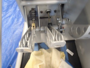
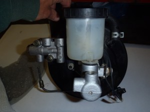
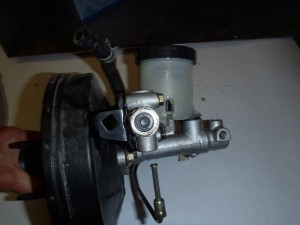
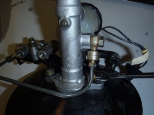
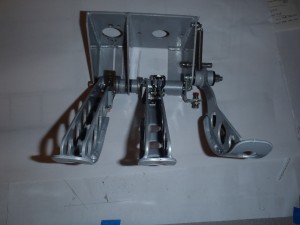
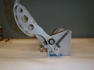
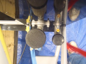
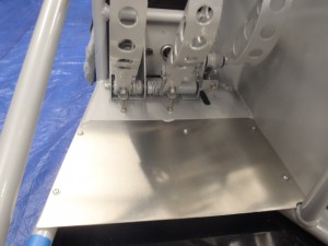
As you will soon see the pedal box in the build manual is for the install of the dual master cylinder box for a bike engine build. So many of the details are different for install of the MNR Miata pedal box. The MNR Miata kit pedal box is designed to use the donor Miata brake master cylinder along with the Mazda proportioning valve and interconnecting fluid line. see pics. I also used the brake master push rod clevis pin so a good idea not to discard this item. The VortX pedal box is a pedestal type. It is very serviceable for it’s job. It is of welded plate construction and the box and pedals are very stiff and will not flex under hard braking. The pedals ratio lengths are correct for use with non power boosted brakes. The pedals use bushings. The box is a tight fit in the foot well. Refer to my floorboard post for positioning in the foot well. My first thoughts as I began, was this is going to be fast and easy just bolt it in and be done with it, but this task soon presented me with some questions that I needed to find answers for. But for builders reading this supplement I hope your install should be more straight forward.
There are a couple of mandatory additions to the pedal box that will be required to make serviceable. I also made several minor and easy modifications to my box that are not required, some I will mention in this install segment and others I will expand upon later in a separate post if there is interest.
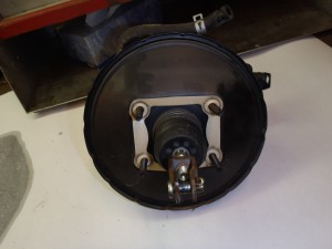
What is mandatory? If your Miata donor was equipped with vacuum power booster (possible all 1.8L USA cars are) you will need to source a suitable pushrod for the donor brake master cylinder and provide means for a brake pedal stop. I did learn a lot for my install by reviewing how the Miata factory pedal box was engineered. The MNR box is very similar to design of the Miata only in a pedestal postion.
But first where do you locate the pedals? As you remember we need to have the box installed with the pedals at the correct position so we can sit in the car with our feet on the pedals so we can accurately locate drivers seat and steering locations. So my first thought, I know I must have full throttle but how much travel is needed for full throttle? So I went to the donor Miata engine’s throttle body and measured how much linear throttle movement I am going to need. I was surprised to find out I only need to move the throttle cable approx 1-1/4” from idle to get full throttle. So I decide to allow for 1.5” of movement and located the throttle pedal so in full forward position until it hit the floorboards, I then spaced ¼” from the floorboard and measured at the throttle cable attachment end of pedal. I rotated pedal to allow 1.5” of lineal movement and note the position and angle of the pedal. Then I needed to make an educated guess were to position the brake pedal in relation to my now located throttle position. I like to have the brake pedal when under braking to be about level with the throttle for “heal & toe” shifting, so I positioned the brake in the fully retracted position so it was about ¾” of an inch in front of the throttle so that under moderate hard braking the pedal will end up near level with the throttle, I hope. So I noted and recorded the position and angle of the brake pedal. I thought I had the pedals in the correct position and am done. Wrong. But at this time I decided to locate a useable brake pushrod. I purchased brake push rod and clevis kit from Summit RacingPart Number RSD-R03 price ————-$9.57
The length as supplied by summit was 6.063 inches and a diameter of 0.355”
The diameter of the Miata push rod( still in the booster) is only 0.263” diameter.
I shortened this pushrod to a length of 4.684” and the last ½” of the push rod reduced to the diameter of 0.263”, this was done because this is the diameter used with the donor car’s Miata master cylinder pushrod. This was done on a lath.
The push rod end acts upon the piston 0.684” below the mounting surface.
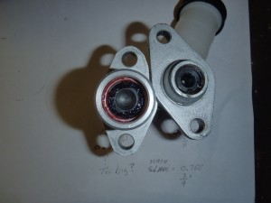
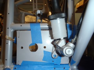
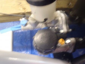
I am sure the pushrod may require some additional shortening to length and I can do this after I determine my final brake pedal position. Possible there is a more suitable push rod that can be purchased and please suggest if you locate one, Possible I should have checked with Mazda to see if they offer a non power boosted brake factory pushrod. The Miata master cylinder does not make any provision to retain the push rod. The Miata uses a brake pedal stop, this prevents the brake pedal from flopping on the floorboard toward the driver, if this were to happen the pushrod could come out of the master cylinder and result in a loss of brakes never a good idea. So this is the reason I will later provide for a brake pedal stop. Now at this time I reviewed the MNR supplied remote reservoir clutch master cylinder and compared to the factory. I note that the bore Diameter of the MNR supplied clutch master is approx 0.80 inches. The Miata has a 5/8” diameter bore. The Miata clutch slave is 7/8” diameter. So Mazda did design some hydraulic advantage to make the clutch easy to push. With the MNR supplied clutch slave I will loose this advantage. I am aware of builders who have used the MNR supplied unit and can not really tell any difference. But since I have plans for a Turbo install and the needed heavy duty clutch that will require I decide to maintain the Mazda diameter of 5/8”. First I tried the factory unit and it does not fit and now you know why MNR supplies the new Girling unit for the kit. I ended up using a Wilwood 5/8” unit part number 260-2636 with integral reservoir I purchased for $49.99 fromSpeedwaymotors. Since I have a brake master with integral reservoir I thought may as well keep all integral, but this almost ended up a mistake and is the reason why MNR provides you with an external reservoir for your use in the kit, but with careful lateral placement of the pedal box can be made to work, this is why I suggest to locate the left vertical side of the pedal box 3/16” from the inside face of round chassis tube in the foot well that is closest to the pedal box. If you locate the pedal box right up against this tube you will have to use the remote reservoir that MNR has provided. It is that close of a fit to use the integral reservoir. The reason being is the clutch master cylinders body and cap is damn close to interfering with one of the chassis diagonal tubes on the engine side of the floorboards. I just got lucky but knowing ahead of time you can use the clutch master with remote reservoir to determine location of pedal box laterally, see previous post regarding floor board install for comments on throttle cable clearance.
So since now I have the clutch master I am going to use, I was ready to get on with it and then thought I better see how much travel the clutch and brake master cylinders require. So I measured the travel of my clutch and brake master cylinders. As it ends up the Clutch and brake have more travel than the throttle! The clutch has the most at near 1.5”! So I have previously positioned the pedals so I have full throttle and placed the brake in clutch in relation to the throttle I now have pedals in position to where I can not get full travel on the brake or clutch pedal. OOPS. So now you understand my Wrong comment earlier. So I have learned you need to position the brake first to allow full travel and then position the throttle relative to the brake and of course double check you still get full throttle travel.
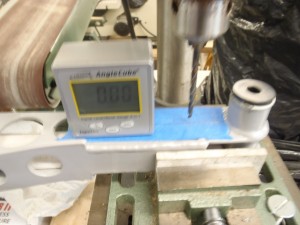
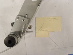
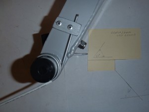
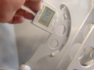
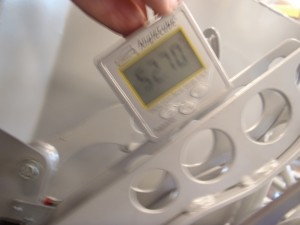
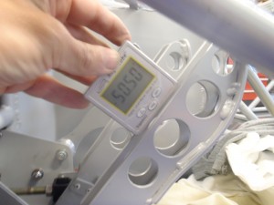
The clutch can stick out a bit toward the driver compared to the brake pedal, and guess what, this is how they are positioned in the Miata. My goal is to provide insightful information to make your build go faster. Since all the master cylinders should be the same( always double check) position the brake pedal so it is at an angle of 52 degree to from the horizontal. I placed the clutch pedal 50.5 degrees from the horizontal and my throttle pedal ended up 58 degrees from the horizontal see pictures. See pics. This should get you in the ball park and save a bunch of time. You can use these pedal positions to determine your final pushrod to clevis mounting lengths and also use these pedal positions to determine where to drill you holes in the pedals to connect for the push rod clevis for the brake and clutch. So that is what I did next. Determine where to drill the holes for the clevis. It is good practice to try to maintain the least change in angle from the horizontal for the pushrods and throttle cable angle.
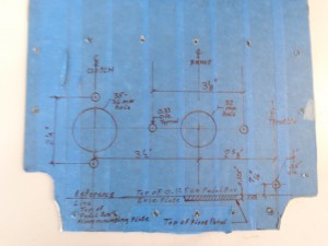
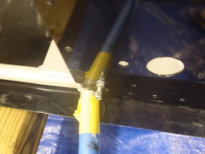
The throttle cable is easy to locate so we will do so first. With the pedal in the idle position just measure the height of the hole from the horizontal face of the pedal box floor and use this same height to locate where to drill the hole in the firewall that is in alignment with the throttle’s cable attachment. In other words a line that is horizontal and level to the throttle cable attachment hole when the throttle is in the idle position gives the least angular change.
I did cheat a bit and lay out in Cad for my use. For a good approximation for brake and clutch hole location( they are the same), first measure the vertical distance from the base of the pedal box to the center line of master and clutch cylinders when bolted into position in the pedal box and record.
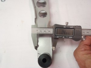
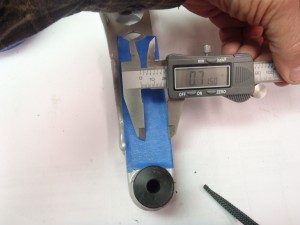
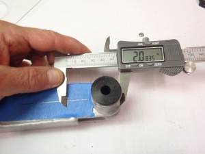
I should mention that I had to do some minor filing to enlarge the hole MNR provided for use for the clutch master and this is to be expected as part of a build. Since you now know where the pedals are when in full back position and the full forward positions you can use a level( provided chassis is level) and locate the face of the level the vertical distance you just recorded from the base of the pedal box on center line of the brake and clutch pedals and mark the face of the pedal that the clevis will be drilled for in the full back and again in the full forward travel position of the pedals. These lines you just marked are not parallel to each other but if you draw a line up from the center of the pedals bushing pivot along the center line of the pedal you can just pick a point between the two you now have a point where to drill. Now this is what I did, but later found out I needed to use my favorite tool again the rotary burr to shave a small amount from each pedal to allow for full pedal travel as I found out the clevis pin would interfere with the pedal and not allow full travel. So as an alternative you could measure the distance you just determined and use a compass and locate this distance(compass radius measurement) more to the forward edge of the pedal or locate on centerline and be prepared to do some filing for clearance, not a big deal. The distance for my install was 2.0835”from outside dia of brake pedal pivot bushing pivot, see pic.
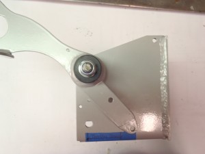
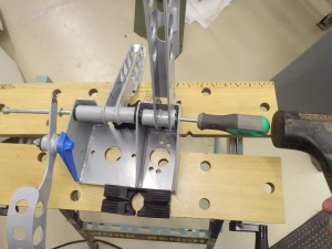
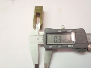
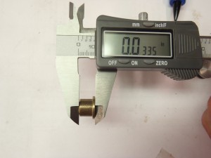
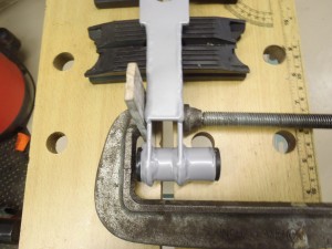
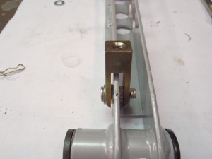
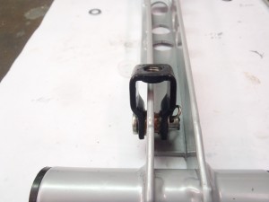
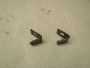
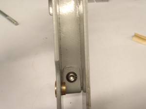
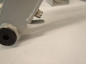
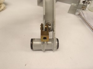
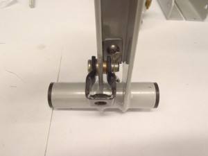
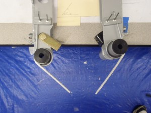
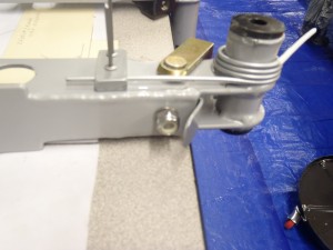
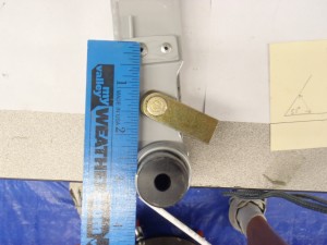
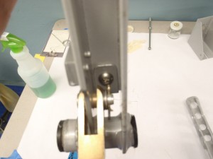
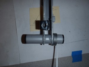
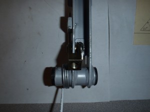
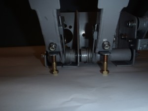
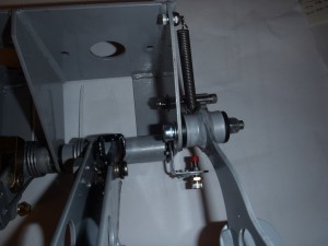
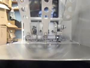
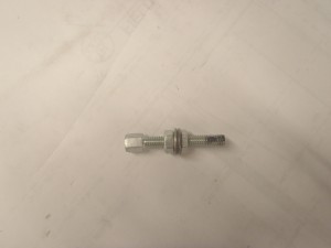
As you can see in the pictures I have made several simple and not mandatory modifications to my box. I decided to use some oil lite bushings at the location of the hole we just located for the clevis pins. The inner diameter of the bushing fits the MNR supplied bolt. So I drilled my hole in the pedals about .002 smaller than the bushing and lightly pressed fit the bushing in the pedal and also used some red lock tite. I also borrowed some of the Miata engineering and decided to use brake and clutch return springs. I purchased the torsion style springs from the Jones spring company,( not related). Since I am required to make a brake pedal stop I decided to make an exact duplicate for the clutch pedal as you will need such stops if using return springs. We can always discuss later if they are a good idea, apparently Mazda did and they are very cheap and easy to install I did so. You can see how I did so in the picture gallery to follow.
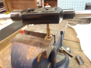
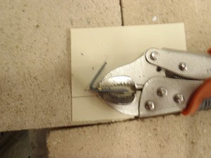
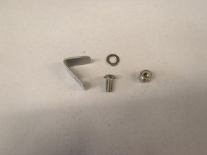
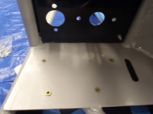
You can also follow in pictures my very simple method of making bent angles(.065 steel) to use for the pedal stops. After pedal box was located and bolted into position I carefully located and drilled the location of the stop bolts into the chassis’s pedal box floor plate, these stop bolts screw into # 10 Rivnuts , I use jam nuts so I can make height adjustments. I also used #10 Rovnuts to mount the pedal box to the MNR welded in floor plate as I found it almost impossible to slide nuts under the mounting plate, be very careful in locating and drilling these holes as you can easily hit the chassis tubing. We are almost done. I found I was in need of an additional clevis for the brake, I used the MNR supplied clevis for the clutch and I just re-used the Miata brake clevis and tapped the threads to suit theSummitsupplied push rod.
We are almost done. I now need to trim the push rods to length and allow enough thread for trackside adjustment. I believe I did need to use a die to thread some additional thread on the brake push rod.
My overall working length of my pushrod and clevis assembly( measured with rod screwed into clevis) from hole in clevis for pivot pin to the end pushrod is as follows. Should have took a picture but the photographer must have been on break.
Brake pushrod assemble overall length = 5 3/8”
Clutch pushrod assemble overall length = 4 ½”
Some commentary. I used the Miata cotter pin and standard cotter pin to retain the clevis pins. I would recommend using quick to remove pin as I am almost certain now I made it very difficult to remove the cotter pin, especially after the body is installed, I should have waited and used a quick release style but it was late and wanted to complete this job. But this did give me an idea. Since I did fabricate a pedal stop for the clutch I really do not have to use the clutch master’s built in stop. The pushrod on the piston end has a mushroomed end that will not fit through a metal washer that is retained by a circlip in the body of the clutch master. So what I did is remove the circlip and metal washer, them I enlarged the hole in washer to allow the head of the pushrod to pass through, so I defeated the cylinders built in pushrod return stop, but as I mentioned I really do not need integral stop when using stop I added to pedals. The reason I did this is I can now easily just unbolt either master cylinders and remove from the engine side of the firewall and will not need to deal with the clevis pin removal to change out a master cylinder. So changing a master trackside should be an easier task. Also I would like to mention that by using the above pedal position angles that none of the pedal ever go past center line in full travel position, but actually in full forward travel the pedal are almost near vertical and this is good practice and why the MNR Box is of a good design.
I recently uploaded a short video clip of the pedal box movement to you tube here
I summarize my installation as a reference guide only for your use, Your build may vary.
1) locate pedal box approx 3/16” from left OD chassis tube adjacent to pedal box.
2) position brake pedal at 52.5 degree from horizontal
Mark centerline of pushrod , below on box floor
3) position throttle pedal at 57.5 degree form horizontal
Mark centerline of pushrod, below on box floor
4) Positon clutch at 50.5 degree from horizontal
Mark center line of pushrod, below on box floor
5) locate and mark centerline of throttle cable for floorboard hole to drill
6) purchase and modify brake master push rod to Overall Length of 4.684
7) mark location of mount holes on floorboards and drill out floor boards to mount master
cylinders
8) locate clevis pin hole 2.0835”from outside dia of brake pedal pivot bushing pivot, see
See pic, verify for you install dimension may vary
9) drill holes in chassis mounting plate for pedal box
10) fabricate pedal stop angles from .065 steel flat plate. Purchase suitable torsion
springs. I can provide if needed.
11) Brake pushrod assemble overall length = 5 3/8”
Clutch pushrod assemble overall length = 4 ½”
12) bolt into position , verify motion of pedals does not cause any interference
f
