Getting started . My first thought is where do I start?
Most build blogs I reviewed do not chronicle the disassembly process in much detail, and why should they as this part of the build is not much fun and is a matter of necessity. But on these pages I hope to post for record the disassembly process I used. I am sure at the end of this parts harvest I will be more qualified to make recommendation of what or how I would do differently.
At this stage of the build I am still planning of using the factory wiring harness and have decided to start this build by removal of the dash and necessary interior assemblies to allow full access for easier removal of the harness.
I started by removing the interior dash panel. Refer to this dash removal file.DashRmv_89_93 This is an excellent tutorial with quality photos prepared by Anthony Meeks for Miata owners for a step by step “how to” for dashboard removal for 1990 to 1993 Miata. My donor Miata is a 1994. I found the procedure to be very similar. On the 1994 there no need to remove the air vent closest to the side widows. There are less screws to remove at glove box. The wiring harness connection will vary somewhat too. But in general just follow the instruction and you will succeed.
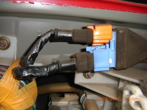
The instruction indicate to be very careful when removing the instrument panel cover. This is an understatement. I did break a clip or two during the “wiggling” back and forth process and I did not think I was using much force. The good news is I believe if you plan on using the donor instrument cluster you may need to “trim” the cover to suit the vortX dash shape and the clips are in the area that will need to be trimmed. But at this point of the build I am not sure and recommend extra caution during this step. Also some notes when you come across the orange/blue connectors, these connector were a bit challenging to get apart.
you will need to remove the orange one first then the blue one see pic, To do this you need to press hard on the orange clip release while at same time pulling back. I found where room permits to use a very small screw drive and using like a tongue depressor press down on the flat tap and pull. The blue will release easily after orange is out of the way.
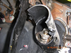
Removal of the top half of the lower steering column U joint protective cover see pic is not covered in the dash removal instruction but is easy enough. You will need a 10 mm socket to remove 3 nuts that hold the column in place. You may need to cut or depress some of the firewall sound deadening insulation to get the socket on , but the good news in comes free after the 3 nuts are removed. I retained this part as it may be useful to serve it’s protection duty in the VortX.
Also I labeled all my connectors as I took them apart.. The system I used was to use self stick labels I bought at Wal-mart. They are about 1/2” by 2”. I would wrap an identification letter/numbered tag around the wires of the male connector and an exact same number tag around the female side of the connector. I also used a permanent marker and noted same numbers directly to the connecter halves. I also used a note book and kept record of every Letter/number of every connector I pulled apart. I would also make a note as to the location of the connecter and if I could determine what the connector is used for in a note book. An example of a note would be D19= steering column, igniton switch gear.
The D would symbolize the general area is the dash, steering column give more precise location and ignition switch gear indicates where the connecter was used.
Often I did not have the third level of location. As D18= Dash, near column, main harness connector. This would mean general area of Dash and was a harness connector. It did not terminate at a device but was junction connection.
You can devise any system you want to use. But I think it to be a good idea to use a system that defines the area. For me D= Dash area, E= engine compartment, T= Trunk, PC= power control module, etc This way when harness is removed you can lay it out with reference to the to the general components of the car.
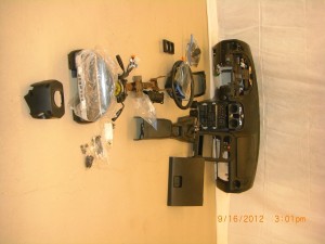
Anyway after following all the steps in the dash removal instructions and 7 hours of time I had the pile of parts removed in this photo.
But we only need the parts in this photo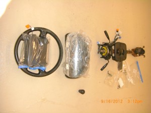 which include the
lower steering column UJ split plastic protection cover.
Steering column with all factory switch gear.
Split plastic switch gear cover and screws. Includes removable 2”x 4” cover.
Solid state instrument panel.
Instrument panel cover
Steering wheel
Gear shift knob.
All hardware for above.
Not pictured but retained for possible use.
Gear shift lever leather boot.
Hazard/pop up light switch.
Center console light.
This ended day one work. Allow about 7 hours but if you work without interruption you will probably use less time.
9-16
What is next?
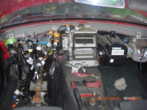
Here is the picture of inside of car after removal of dash. Here you can see the maze of wires and I must admit this can seem a little intimidating as this stage.
For lack of a plan I removed the seats. This was easy enough. Only 4 bolts per seat. My passenger seat required and extra bolt to remove for the shoulder harness. I believe I used a 24 mm socket. I now find the room to work has improved and since we are not going to reassemble our car, I would recommend making this the first step before dash removal as it will make working under the dash more comfortable and takes only 10 minutes.
Next up. As you can see in above picture the the main wiring harness disappears behind the heater core housing and blower fan housing. So these are my next targets for removal.
