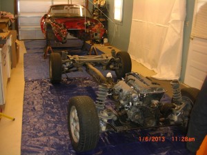
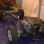
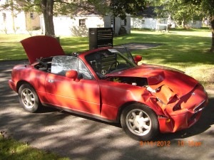
As I mentioned in my last post I now am turning attention to removal of engine and transmission unit. I have decided to do this by separating the body from the power train chassis unit. To explain if you are not familiar with the design of the Miata. The engine mounts, engine and the entire front suspension are mounted to a front sub frame. This front sub frame is bolted to a PPF (Power Plant Frame) which is basically a stamped C shape channel that connects to the transmission at the front and connects to the rear differential which in turn is bolted to the rear sub frame and the entire rear suspension. The body unit is connected to the front sub frame by 10 bolts and to the rear sub frame by 6 bolts. So the plan is to separate the body unit from this chassis unit and lift the body unit high enough and roll the chassis unit forward and set the body unit down on Jack stands. This will allow me unrestricted access to remove the wire harness from the body unit and easy access to all donor parts of the rolling chassis unit.
As a prerequisite please read Chapter 3 pages 3:1 to 3:11 and especially sections 4:1 to 4:81 in the manual to prepare for this procedure. IMPORTANT if you plan to remove the body as a unit as I did in my build do not proceed farther than step 4:81 in the manual.
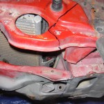
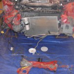
It is my opinion I would definitely remove the radiator with fans attached and AC condenser if your car is so equipped. You will find this recommendation in the instructions in the manual, but not until instruction 64, that in retrospect the writer would recommend removal of the radiator and fans. In my case as you already know I had no choice do to crash damage. But having completed this process I certainly recommend to do so and may actually recommend to go ahead and take the ½ hour of time to saw the core support out of the way especially if you plan to scrap the body unit. This allows you much easier access to remove some the engine harness connectors which for me were the most time consuming part of this process.
Essentially just follow the instructions in the manual starting on page 4:1 section 4 Removal of engine (with transmission). I will add my comments to number instructions in the manual.
10) This shift boot gator has a formable base, so I place this part in a new pile of parts that I have designated “maybe” in other words not to discard at this time as they may have a possible use in the kit such as this boot gator, this one seems a bit too heavy in weight for my liking. So I now have 4 designated piles. The Required pile, the e-bay to sell pile, the scrap pile and now the “maybe” pile.
17) & 18) at this stage I did not drain fluids, can if you want as you will want to change later.
38) My car used 14 mm socket not 17 as noted.
43) Believe it or not removing these clips on the oil cooler hose on right side of engine for me was rather difficult and took me too much time, this is why I recommend removal of radiator as this allows you better access. Patience required.
47) Be prepared for this step will save you some time. I did not up until this step remove the fuel system pressure as recommended in manual previously. I would wait until now as you can use the fuel pressure to siphon the tank. Get yourself 5 ft of 5/16” I.D fuel line and have on hand enough gas containers to hold all the fuel you have in the tank. Put you fuel container in position and put one end of drain hose in it. Remove the hose clamps as noted in 47. The hose that connects to the front of the fuel rail is the supply line and will be under slight pressure. Have small plastic (I used an old cool whip container) bowl to collect any spilled fuel. As soon as you pull the rubber hose off the metal (from tank) supply line quickly slip one end of the 5/16 fuel hose on and you will find pressure and ensuing siphon action will drain your tank! My car had more fuel than I thought and I had to vise grip my drain hose so I could make a run to the local Wal-Mart to buy another 5 gal gas can.
61) I deviated a bit here. Using 10 mm socket I removed the bolts that held a metal angle that secures the radiator inlet metal tube to the left front inner fender. I then removed the hose clamps from the water pump inlet casting. I did this to allow better access to the AC and power steering pumps. My notes were a bit vague here, but around this time I also remove the power steering supply and return piping that looked to be in my way. For a car you plan to put back on the road you would not want to do this. But we have no use for the PS rack lines so off they went and out of the way.
70) Not necessary to remove O2 sensor if using the body as a unit but can if you like.
71) I removed exhaust from down pipe back including the catalytic converter. Save the converter.
74) Not necessary to remove slave from transmission. I simple disconnected the slave’s metal supply line at the chassis attach bracket, leaving the coiled line still attached to the slave. But you can release metal line at slave if you like. I removed the slave cap and put some plastic food wrap over the top of reservoir and replaced cap to prevent spills. This worked for the slave but not for the brake lines.
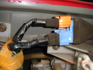
77) This went easier than I thought. You will need to reach between top of transmission and body to release metal harness clamps. The clamps bend easily. This will allow you to pull the harness toward the passenger side a bit to release the two white connector from the passenger (RT side forUSA) that goes to the neutral switch. I could not get the two black bullet connectors to release. So as the manual suggest I used a 1” open end wrench to unscrew the reverse switch from the transmission. But be careful here. On my car there was some black electrical tape wrapped around the two supply wires about 2 inches from end of switch. You will need to remove this tape, If not the wires will not be able to “twist” when you unscrew the switch and will assuredly break.
79)-81) make sure the supply harness is free from the PPF and power train.As noted in manual there are severe plastic harness clamps that attach to the vertival face of the PPF from the transmission to the differential.All these plastic clamp need removed. Just leverage them from the PPF. My car had an appox. 1 inch square plastic harness to body support in the location near the right rear wheel area that was removed using a 10 mm socket. This support was not noted in the manual. I also believe I had an additional body ground not noted. So just a heads up as your car may vary so just be careful to make sure the harness is free of the PPF. Remember the harness will stay with the body when it is lifted to separate it from the PPF and sub frames.I used some twine to tie the now loose harness out of harms way.
IMPORTANT! Stop at step 81 in the manual do not precede with steps 82 to 95 if you intend to remove body as unit as you need to leave the PPF attached to the transmission and sub frames.
AT this point I was no longer following the manual, usually dangerous for me. I looked the over the job, keeping in mind we are going to lift the body off to see what would cause interference to this process.
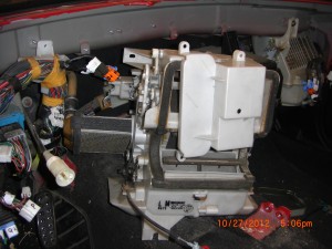
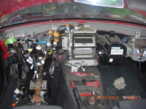
So I removed all the AC supply and return lines and brackets. I used some twin to tie the main wire harness out of harms way. I removed the speedo cable and put in the donor pile, you will need it if you use the Miata instrument pod.
I released the front and rear brake flex lines at body bracket, because this seemed easier access. I left flex lines attached to calipers, but you could release at calipers.
Next I disconnected the E brake lines from pivot arms. Use 12 mm and 14mm sockets. Loosen cable from bracket, slide cable out of arm and using pliers rotate cable bug 90 degrees and slide out of arm, easy.
At the front I removed the U shaped sway bar brackets from the body.
You do not need to remove the sway bar from the suspension but you must remove these brackets as these brackets are the only front suspension parts that connect to the body. Note there is a vent hose that connects from the charcoal canister to a static area in the front sub frame on left side of frame, this was not noted in manual. Pull this hose off plastic connector. If this was an airplane this would be a great place for a Pitot tube static port.
I finally am satisfied all is clear to lift the body. So now is a good time to decide how I want to lift the body. But first I decided to remove some body parts for the e-bay for sale pile; this also has the benefit of removing some of the weight we need to lift.
So let’s remove the doors. Refer to chapter 11, sec 9 door in the manual. Using a screw driver lever the plastic grommet from the door post and not the door as manual indicated and pull connectors through grommet hole and separate connectors. Use 12 mm socket to remove hinges. If you leave the door shut to support non hinged end, them remove the hinge bolts. Then with on hand supporting the door near post and opening the door with other I was able to remove the door without assistance, but would be easier with a helper. Be careful I almost dropped the first one. But I had a place a cardboard box just in case, I needed it.
Next I removed the trunk lid see chapter 11, sec 6 in the manual. Use a 10 mm socket to remove trunk light harness connector to trunk lid.
Next up tail lights refer to chapter 7, section 30 in manual. 10 mm deep socket required.
Remove the license plate lights and brackets.
Then I removed the rear bumper and fascia and side marker lights as one unit as outlined in chapter 11, section 9.
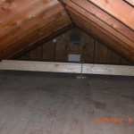
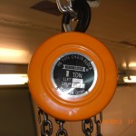
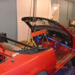
Well now back to how to lift the body. I have never done this before so I am not sure how much lift I will need, so I guestimate is in order. I decide I will leave the damper struts attached to the lower suspension arms, so I will need to lift the body unit high enough for the rear dampers to clear the under body as I roll the chassis forward. I roughly estimate 24 inches of lift should do it. I have a standard ceiling height. I have at least 32 inches from top of windshield frame to ceiling clearance and the body is currently sitting on 20 inch jack stands. So I should have plenty of room after the car is sitting on its tires, this is good news for any builders working in shops without high ceilings. I have a crane style engine lift and I also own a 1 ton harbor freight chain hoist. My original plan was to use two chain hoist one front and one rear as I would not have to concern myself with balancing the body during the lift, but I decided to be brave and cheap and use the single chain hoist with the $25.00 Harbor freight 2 ton load leveler I bought previously for engine removals. Caution must be used here. Again I am estimating I will be lifting a body unit weight just shy of 1000 pounds or so. So you will need to be use good judgment in how you attach the chain hoist to your ceiling supports. Consult a professional if needed. In my case, my ceiling joist are 16inches on center and 6 inches in depth. I constructed two beams using four 2×4 x 8 ft. I screwed two 2×4 by eights togetherto make each of the support beams. I place each support beam across 6 of my ceiling joist within 2 feet of the bearing wall supports. If my joist were 2 ft on center I would have used 2×6 min material for the support beams. I could have used say a single 2 x 8 x 10 at the center line but I did not want to apply the vertical loads where they would create max bending moment on the ceiling joist, this is why I used the two separate beams located within 2 feet of the end walls. I then nailed together two 2x6x10 to make a crane beam with and additional 2 x 4 x 8 cap plate centered over the 2×6 x 10 beam. The chain hoist will contact the 2 x 4 cap plate portion of the 2 x 6 x 10 support beam the 2×4 will act to distribute the point load across the 2×6 beam. See picture of my set up.
Please excuse this rather long description of the chain hoist support, but proper design consideration is a must otherwise serious injury or damage may result, further as a disclaimer I make no recommendation or fitness or suitability for use or guarantee of safety for anyone who copies my support set up. Please be careful.
I attached the chain hoist to my crane beam with chain with a load rating of 2000 lbs.
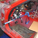
But where to attach the load leveler? I made a guess and dropped a plum bob and locate the hoist line 2” to rear of windshield. If you are following along locate the hoist line 7 ½” to rear of windshield, this will get you closer to the balance point. I used the chain supplied with the 1 ton load leveler and attached using the bolts used to locate the center console. I had some concern here the spot welds in this bracket would hold, so as a safety net I attached 1000 lb capacity tie down strap to the front load level chains and to the door hole bolts, I used larger fender style washers to prevent slip off.
I bought a 5ft length of min 1000 lb working load chain and used it instead of the shorter chain provide with the load lever and attached this chain using the shoulder belt bolts with large washers. You want the chains connected to the load level to be inclined greater than 35 degrees from the horizontal.
I am now almost ready to lift the body but I still have to remove the bolts connecting the front and rear suspension frames to the body and the bolts connecting the shock towers to the body.
So using a 14 mm socket loosen but do not completely remove all 4 shock tower mounting nuts, there are two nuts for each shock . Do not remove the larger central nut covered by a dust cap, or the shock unit will separate under considerable pressure. If I remember you may need to remove the left side trunk trim panel the hides the fuel supply filler tube first to get access to the rear left side shock nuts.
Now time to remove the large diameter bolts that mount the sub frames to the body. You can refer to the manual page 8:12 for illustration. Remember our car is still supported by jack stands located on the body unit and not the power frame unit. So essentially the engine and PPF is hanging from the body unit.
I made a purchase of a ½” Harbor Freight (OK there is one near my location) 700 ft lb torque air Impact gun (called the Earth quake, about $100.00 to assist in removing the body frame bolts. Use 6 point impact sockets. I should mention using the recommended 90 PSI pressure this tool worked great and made easy work of removing the body bolts.
At the front each end brake loose only but do not remove the 2 bolts using 19mm impact socket located near each front shock tower. Then break loose but do not remove 1 bolt using 17 mm Impact and 2 bolts using 14 mm impact socket at each front corner of the front sub frame. In total there are 10 bolts that hold the front sub suspension frame to the body. WARNING. Do not remove bolts, only break loose. Remember our engine and PPF is hanging from the body unit. If you remove these bolts at this time the engine and front subframe will fall on you and you will die! After front bolts are broke loose I turn my attention to the rear suspension frame. Refer to the manual page 8:25 for an illustration .You can review in the manual chapter 5 rear subframe removal on page 5:15. Most of these steps we have already completed. Do NOT remove any bolts that connect to the PPF Unit! Using the impact or suitable breaker bar and 6 point 19 mm impact socket brake loose only( remember, the remove and you will die part) the 3 bolts each side that are located in the area of the shock towers. They are easy to find.
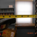
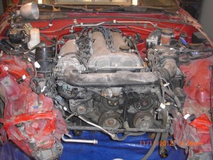
At this time before I change our support base I thought a good time to take some engine to firewall clearance measurements. The cam position sensor is close to the firewall. Actually the Mazda firewall is recessed in the center to allow clearance. The distance from sensor to recessed fire wall is 1 -1/2 inch. Likewise the distance from the coil back to firewall recess is 1 -1/2 inch. The area of closest interference is the EGR pipe, which is only ½” at closest location to fire wall. The firewall offset by the way is 1 ½ inch.
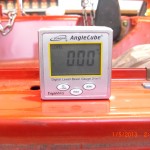
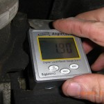
I also wanted to measure the angles of the motor, transmission, driveshaft and rear differential. I was going to reference this angle to the door sills. But using my digital level the door sills were actually 0.00 absolute level, could not do that if I tried too.
The level positioned on the valve cover is 2.10 degrees sloping to rear, hi in front.
I recorded a 2.10 at the engine oil pan. I measured the bottom of the transmission at where it connects to the PPF also at 2.10. The driveshaft at 2.80 and the rear diff at the flange that connects to the PPF at 1.95.
I wanted to make this info for record to use as reference for fitment of power train into the VortX for comparison to the factory driveshaft angles.
Now we need to move our support base. Install all for wheels and tire and snug wheel lugs, no need to torque. At this time I jacked up one end of the car at a time, removed the 6 ton support stands and replaced them with car ramps. I position the front ramps facing forward (like you would drive off) and at rear the ramps as you drive on them. Now all 4 wheels and most importantly the engine and subframes are support by the tires on the ramps. We do not have brakes, so make certain the car can not roll front or rear. Nice thing about ramps position as I have they prevent this movement.
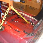
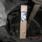
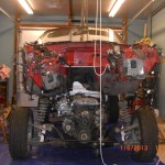
I have a concern about what is going to happen when the shock towers are unbolted and when the body is lifted I believe the suspension will collapse onto itself and the chassis will possible drag on the ground. Certainly making it difficult to roll the chassis out from under the body after is lift. So to prevent this possibility I went to the lumber store and bought a 2 x 3x 8 utility stud. I then cut (4) 7-3/4” pieces or wood support struts from this stud. At rear I placed one end of 7-3/4” piece near outer lower wishbone. I used duct tape to position this material so the top end will contact the upper part of the subframe upon collapse. I repeat at other rear side. See pic.
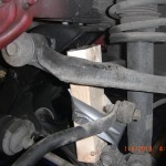
At the front I place one end of wood strut up against sway bar mount on lower wishbone and again using duct tape positioned the wood so the upper end will contact the front subframe. See pic.
I am going to give some instruction slightly different to what I did. For reference at this time I completely removed all 8 shock tower bolts. I am going to suggest now to leave the front tower nuts several turns on. Now that the car is on safely on the ramps you can go ahead and remove completely remove the subframe to body bolts. Note at the front when the last bolt is removed the body made a rather startling pop and jumped up. This certainly got my attention and I did not expect. But what happens is the front spring preload is such that as the last nut is removed the spring quite abruptly forces the body away from the subframe. So this is my suggestion as to leave the upper tower nuts a few turns on as this should limit this explosive action. But no harm was done, and when removing the other side bolts I was expecting this to happen it was not a big deal. But it does shake the body a bit and you want the car securely supported and make sure it can not roll. I actually do not know what would happen if after all front body bolts are removed and then you follow my suggestion and remove the front shock tower bolts from above since I did not do this. Some of the preload will have already been released. But I would use caution removing these bolts if you try this method.
At the rear use 19 mm socket to remove the rear subframe to body bolts. Thespring preload at the rear is not an issue to be concserned with. Now we are almost ready to remove the body. We just now have to get the tires back on the ground. Carefully jack the car up, place the jack on the center of front subframes, lift and remove ramps and lower to tire. At rear I placed jack using a wood spacer on the rear part of the PPF near the diff to lift car, remove ramps and lower to tires.
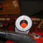
It is now the moment of truth and time to lift the body off the frame. I position a level on the transmission tunnel of the body to assist in maintaining a level lift. See pic. One more quick look around to make sure the harness, brake clutch lines, are all disconnected and free from PPF, engine and any part of the dive unit. I recommend an assistant for this part, this was the first time I used an assistant. For me I asked my neighbor Drew who is retired and a car enthusiast and currently restoring a “doodle bug”. I had Drew assist by operating the chain hoist while I would observe the lift making sure all is clear and the body lifts free, at the engine compartment you want to make sure the body clears the cam sensor. On my car the throttle position sensor and the throttle body linkage required some tending to. We lifted the body in 3 inch increments, and then I would do an all clear check, repeated this several times. I did have to adjust the load leveler; I would not attempt a single point lift without using a load leveler. After we found the balance sweet spot we hoisted the body until the door sills were 34 inches above the ground this allowed at least an inch clearance.
You notice I also have some rope attached to the front and rear of the body. I tied these ropes off as a safety precaution to prevent to body from tilting. I simply pulled in the front sway bar and easily moved the chassis forward and clear of body. I position by jack stands in position at the same 20 inch height as before and lowered the body till lift cables are slack.Mission completed. It is nice when a plan works according to plan.
At the end of my last post I asked the question if this method of power train removal would either be a good one or a dumb one.
Having completed this, It was a GOOD idea. I would certainly do this again. I do not think it takes any more time this way. There were several steps in chapter 4 from 82 to 95 you do not have to do. It only takes about a ½ hour or so to loosen the body bolts. Now I am in a position where I have unrestricted access to remove the rest of the harness from the body unit and the same goes for the separated power frame unit. I should also make say I had a good donor car to work with. It has very little rust and came apart easily. As a help hint I typically would spray the next days bolts to remove at the end of the day. This may have help make this car disassemble easily. From start to this divorce of body and power unit I have about 27 hours invested so far. I am not counting my time to take e-bay pictures, or time to build the crane support and certainly the time to write this blog.
I will make one final comment. I forgot to measure the height of the Miata door sill before the lift; I would guess this around 10 inches. So if you have a simple engine crane with a 1000 pound lift capacity and have a lift range a little over 24 inches this should work fine. If the crane could be positioned so the legs could be roll from the rear between the Miata’s rear tires, this would be the easiest way to go, especially if you only plan on doing this procedure once.
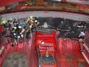
Next is to finish removal the main wire harness from the body unit. I should be making post more often.
