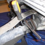
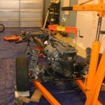
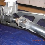
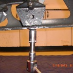
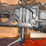
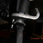
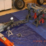
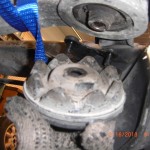
Before moving to the front calipers as I mentioned on my last post. I decide first to disconnect the rear prop flange from the rear differential flange. Refer to page 4:2 in the manual. Use a 14 mm socket and 3/8″ drive socket and moving in a diagonal sequence first loosen and then remove the 4 retaining nuts and bolts.Bag and label fasteners and put into the donor pile.Slide the drive shaft slightly forward to clear differential flange. Since I have yet to drain my fluids at this time I did not remove the prop-shaft, I simply tied up with twin for the moment and moved to the front calipers, but now would be a good time to drain fluids and shaft.
flange bolts removed and prop-shaft slid forward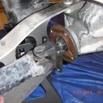
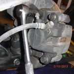
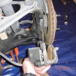
As I left off on the last post I next removed the front brake calipers and rotors(temporarily). Refer to pages 9:10 in the manual for instruction. Use a 14 mm socket to remove the 2 caliper to upright mounting bolts.
After you have caliper removed repeat for other side and put the calipers and mounting bolts into the required donor pile of parts.The brake disk is now free and and can be lifted off of the hub and removed. You will need to do this in order to set up your dial indicator and check the front hub bearings for play. I did not bother to check the any of the brake disk for run out as I intend to use performance slotted disk all around, but if you are re-using the disk now would be a good time to check the disk for run-out. Refer to manual page 9:10 for instruction on run out check.
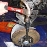
Refer to page 9:21 in manual. I needed to use a wood chisel to help separate the rather tight front hub dust covers. I position the sharp edge of the chisel at the seam( looking for the widest part) and tap chisel with hammer and moving in a circular pattern continue the tapping until you have created a small gap. Then you can use a pry bar or more blunt end screw driver and hammer to further separate the dust cover. Then you can grab with channel lock style pliers and remove completely.
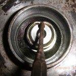
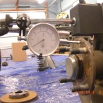
Next in similar fashion to what I did at the rear, I set up my dial indicator to check for lateral play of the front hub bearing. Max allowable play is .002, Mine was less than .001, so they are usable. Reset the dial indicator and repeat check for other hub.
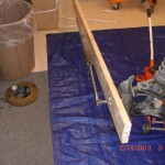
After this wheel bearing check. I prepare to loosen the hub retaining nut and used a drift punch to straighten the hub nut stakes prior to loosening hub retaining bolts this is the same procedure we already did for the rear. Using 1 1/8″ socket with breaker and pipe extension for leverage and the 2×6 SST in place to prevent the hub from rotating I used my weight as I stood on the pipe and broke the 159 Ft lb tight hub nut loose.
I should note I did clamp a pair of channel locks onto the steering rack shaft as the wheels wanted to turn when torqued.Repeat loosening procedure for other side, but do not remove hub nut and hubs at this time, I just want to break loose while I have the engine weight and PPF in place.At this time I replaced the brake disk and replaced both front wheels and tires to allow a stable platform to support engine weight while I return my attention to removal of rear differential.
As we are now ready to remove the rear differential I drained all the fluids. Use a 24 mm socket for the rear differential and the transmission drain plug and 19 mm socket for the engine drain plug.
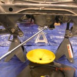
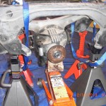
I did use some cheesecloth as a screen to train the tranny oil into just to see if there are any big pieces of metal that should not be in the oil. There were none, good. Which makes me ask, is there an aftermarket source for magnetic miata drain plugs, may be a good idea to use one. Next I decide to remove the PPF, In doing so the front sub-frame and transmission and rear sub-frame with diff and control arms still attached will need to be able to support themselves independently.So in preparation of PPF removal I support the rear sub-frame with 4 jack stands. I support the transmission with a single jack stand and the front sub-frame is supported by the wheels and tire which we put back on. For safety , I did wrap a couple of strap tie downs around the diff just to make sure it would not hit the floor if it slip off the jack during removal. As it turned out this was not necessary,but why not.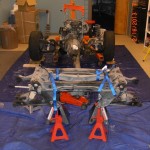
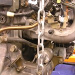
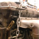
An issue I had was where to attach the chains to pull the engine. The manual says to use the factory engine removal hoops to attach the chains to. Well my car does not have factory engine removal hoops. On the drivers side at the front of the head near the valve cover part line is what looks to be where the hoop is located in the manual is a bolt hole that may work, but diagonally on the passenger side rear there is not counterpart. I do see some potential holes but all the potential suspects on the head do not seem substantial enough to me and I am reluctant to use for fear of cracking the head. So after looking around, I decide to partially remove the upper most starter bolt and attach a chain here for the passenger side rear , and at drivers side front I attached chain to the old and now unused but very strong AC compressor bolt. See pics. But the concern I do have about these location is not the strength but whether the C of G of these locations is high enough to prevent a rotation during lift. It may not be ideal but I believe I am good. We will find out soon if these are good hoist attach points.
I attach the chains properly using by load leveler and position the engine crane in position and apply a very slight preloaded to chains just to make sure all is secure. So now I have the rear sub supported by 4 stands, the front sub-frame supported by wheels and engine hoist and tranny by jack stand and a floor jack in position below the rear differential
.
So now we are ready to proceed and should have all our supports in position to finish the harvest. Next I break loose and loosen the rear differential carrier mountings. I want to loosen these carrier bolts while the differential is still attached to the PPF so we can use the weight of the PPF to torque against to loosen the carrier mounts. For reference page 4:27 11.0 .
Use 12 mm socket to loosen two nuts and 17 mm socket to loosen larger center mounting bolt that is torqued to 62 to 72 ft lb. Just loosen for now. Repeat for opposite side carrier mount. We will remove carrier mounts after we have removed the PPF.
Since all fluids are drained and there will not be any oil to be spilled. I now removed the prop-shaft from the transmission tail-housing . Just slide the pro-shaft rearward and it almost removes itself. Some builder have the prop-shaft shortened to suit the VortX. The factory Miata does not have serviceable U joints. I will be using a custom length drive-shaft with serviceable U joints. These custom drive-shaft will be available from Fastcraft motorsport for approx. $249.00 and you have a shaft that can be rebuilt.So for me the prop-shaft is for the e-bay pile. But some builders do use it and this is a viable idea if you have a local shop that can shorten the donor shaft.
Refer to page 4:3 in the manual for PPF removal instruction.
First remove the support bracket between the transmission tail casting and the PPF. Usa a 17 mm socket to remove bolt holding bracket to PPF and 14 mm socket to remove 2 bolts holding bracket to transmission . I am not sure at this time if this bracket is required for the VortX so I bagged up this bracket and hardware and placed in the “maybe pile of parts”
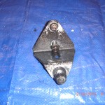
At the front of the PPF two long bolts attach transmission to PPF. Use 17 mm socket to remove these bolts.
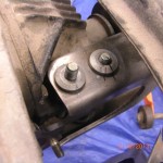
Top view pic .Witness marks per manual.These collars are not removed to remove the PPF.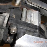 view of differential spacer. This is used for the VortX
After both bolts are removed you need to remove the “collar” located at the bottom of the PPF at the front bolt location. This collar passes through the PPF and the inner part inserts into the differential mount casting.There is a ready made relief in the rear of this collar to insert a pry-bar. Use some WD40 to assist. I had a pry-bar the exact size needed and was easy to start, but do not pry too hard as you will only jam it as you pull form one side. After I got it started I grabbed in by hand and tapped it with a hammer and it easily removed. This must be removed. Once removed we are read to remove the PDF and split the car in half so to speak.
We are now ready to remove the PPF as it is free. At the rear it can be move sideways until clear of the differential casing. Some wiggling and some WD40 may be helpful here, once free of the rear differential casing you can easily pull the PPF rearward to remove from the transmission casing.The PPF is surprisingly light, seems to weigh less than 20 LBS.
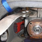
The donor is now split in half and we are ready to remove the rear diff now supported independently by 4 jack stands. First position the floor jack under the differential to assist removal.
Refer back to manual page 4:27 11. Now that the PPF is removed from the differential we are ready to completely remove the the differential carrier mountings. Use 12 mm socket to remove the two carrier mounting bolts and 17 mm socket to to remove the center bolt. Repeat for other side.
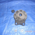
The differential is now free and can be lowered with the floor jack to ground.
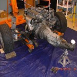
I like this picture as it is all that is left of the original donor and the disassembly will be the subject of our next post.
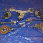
This is a group portrait of the rear drive-line donor parts
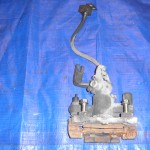
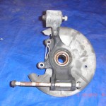
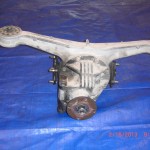
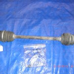
Some “before” pics of donor parts to be used to compare with after refurbishment.
Well that completes this post and I can see the finish line of the deconstruction process, after-all there is not much left.


