I still have a few donor parts to refurbish but I am anxious to start building and want to take a break from the mechanical refurbishment tasks.
So time to get on with the build. Actually I am farther along with build, but am very tardy with keeping up the blog so will try to get caught up shortly.
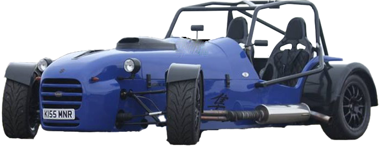
This post is to supplement chapter 2 of the MNR build manual.
As is typical of late,I will post photo’s at end of word copy as a gallery for reference.
My general build order is to start with and install the floor boards and pedal box. Then install the steering rack and column with wheel along with the drivers seat. The reason for this order is the pedal box with the pedals in correct position will need to be installed first so driver can locate seat and steering wheel placement. Wheel placement is required to determine final length of steering column shaft. Naturally seat location and final steering wheel location will vary from body type for example long verse the short legged.
The pedal box location is predetermined. So the pedal box will dictate our starting point reference.
Installing the floor boards is the first order of duty, but even this seemingly simple task can not be accomplished without some reference to the pedal box. I should say that I chose to drill hole location in the floor boards prior to final riveting to frame, though many builders will simple install the floor boards and the drill out the holes in floor boards to mount the brake and clutch master cylinders, to each his own, you can decide which is best. I will deal with the pedal box in a separate post to follow and recommend to builders to review the pedal box post prior to install of the floor boards. I should also mention that the pedal box as supplied by MNR for the Miata kit is subject to change, so dimension shown in my install may not be exactly the same as on your kit, but nevertheless the procedure and reasoning should be the same. Some general comments before getting started, the MNR pedal box is designed to use the Miata master cylinder and Miata proportioning valve. The Miata clutch master cylinder does not fit, I know I tried. MNR does supply a clutch master with remote reservoir and necessary braided steel lines and fittings!
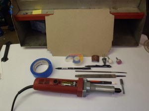
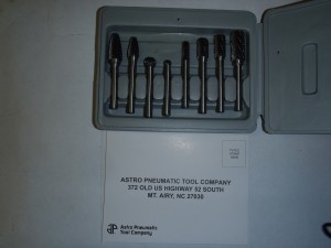
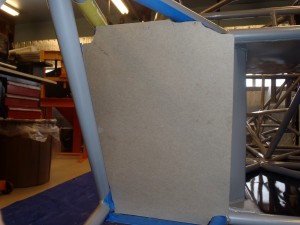
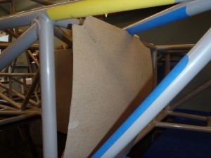
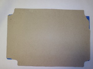
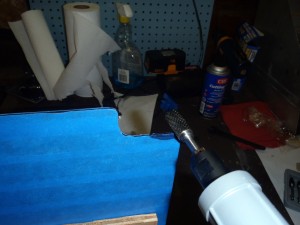
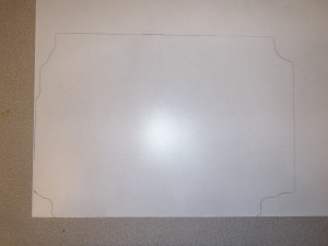
First you will need to trim the supplied and notched out power coated floor boards to fit. You will find you will need to do a bit of trimming to allow clearance for the tubing at welded clusters. I found some suitable cardboard and I traced the outline of the floorboards and cut to shape. I would position the cardboard and mark interference points trim and retry until I had a good fit. In retrospect at this time I would have used clear plastic possible instead of cardboard. As later I as you will see I transferred the cardboard final template shape to clear plastic sheet to make it easy to exactly locate the center frame tubes. See picture of tools required. I would like to say the Astro Pneumatic rotary burr set available on Amazon or e-bay is a mandatory tool to have for building a kit car as I have used it many times, if you do not have one order it at this time or another brand, but this brand is reasonable priced and seems to hold up to use and I can make a recommendation.
Next I wanted to determine where to locate the pedal box laterally left to right. As you will soon find out the pedal box is a very tight fit, this is due to the Miata bell housing being of larger size than for Bike engine VortX or the UK type 9 transmission commonly used with donor Sierra cars. It is this lack of space that makes it not possible to fit individual front and rear brake master cylinders with a mechanical bias bar adjuster. More on this in the pedal box post. For my example I located the left pedal box side plate 3/16” from the face the he closest vertical chassis tube for left hand drive car.
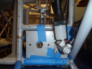
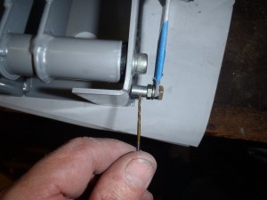
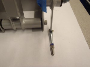
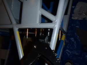
But at this time you will need to determine how you are going to mount the throttle cable to the throttle. As you can see there is not much room between center line of throttle and vertical chassis tube near transmission tunnel. Remember to leave enough room to allow for the diameter of the jam nuts( and washer)that will be used to located the cable on each side of the fire wall. See picture. I at first was going to locate the C. line of cable closer towards the pedal box. You can buy after marked products to do this. I determined on my pedal box that room would not permit and decided to use a clevis style set up. I should mention that most builders just simply loop the cable around the hole in the throttle and used supplied bug to hold cable end. This probable will work fine, but did not want the moving surface of the pedal to “wear against the cable”, hence reason to use the clevis and also since the clevis is also on the center line of the throttle so I can always fall back on the simple loop set up, but I could not if I decided to use an off center line means of attachment. So my advise is to locate the center of the throttle as far to the right(left hand drive) as possible or to at least try to get the prior mentioned 3/16” or better ¼” clearance at left side of pedal box to chassis tube. This clearance is needed to allow alternate clutch master cylinders but the 3/16” clearance is not required if using a remote reservoir.
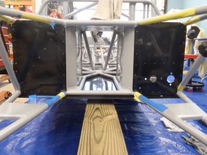
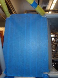
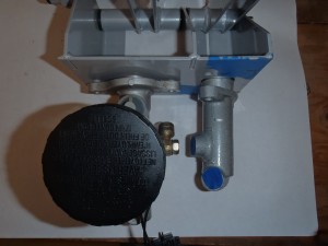
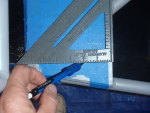
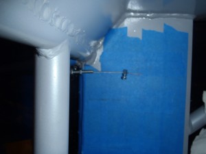
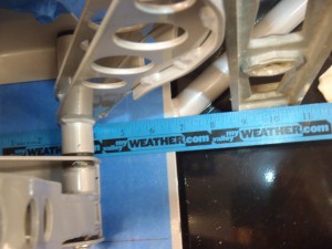
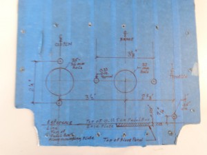
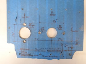
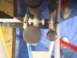
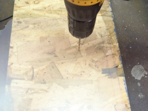
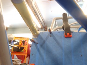
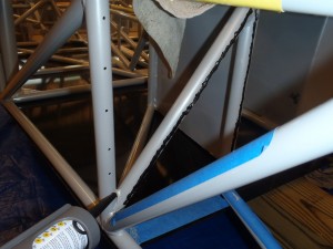
Once the lateral location of the pedal box was determined I located the center lines of where the push rods for the brake pedal and clutch pedal will be located and transferred these C.line locations to chassis and marked onto blue tape, see picture. I covered the black powder coated floor boards with blue painters tape to protect them and make easy to read dimension lines. I then located and dimension all hole cut out locations for the brake and clutch master and also the throttle cable hole. Please be aware the 7/16” dimension location for the throttle cable will most likely not be the same for your kit. This height will need to be measured after you have located and positioned your throttle in the pedal box. This could be drilled at a later time if you want. But this location does vary. I will go into more detail in pedal box post. I show picture of final install to make reference to tight clearance and show a picture that explains why the Miata clutch master will not fit properly. Now that I have measured everything at least 20 times I finally got the courage to drill the floorboards, see pictures.
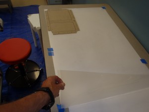
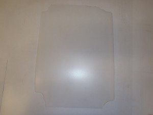
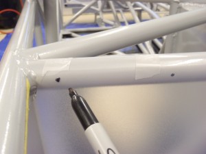
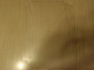
Now that the floorboards are cut to fit and drilled I just need to locate them and drill the holes on the center lines of the round chassis tubes. To make this easier I decided to trace the finished templates onto clear or translucent plastic sheet, see pics. I then cut them to shape using an Xacto knife. I then located the center lines of all the chassis tubes and marked the center line with a black dot. This is easy enough to do using a level orT Squarewith face perpendicular to chassis tubes. I then noted two holes one Vertical and the other horizontal as “C”ontrol marks that I will use to determine correct final positioning for drilling. I placed the plastic template in position and looking “though” the template I simply marked the center lines of the chassis tubes and the two “C” marks on my clear template. I removed the template and connected the dots and marked approx every 2 inches locations on the center-lines I just drawn on the plastic template for my drill holes, and I made sure to drill holes on my “C” mark locations. See pic of drilled plastic sheet.
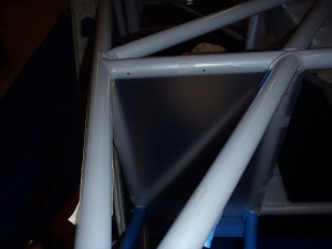
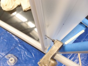
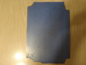
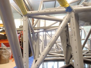
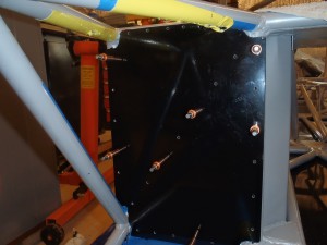
After this step I just simple taped the sheet to the floor boards and match drilled using #30 drill bit. Typically use #30 drill for nominal 1/8” rivets as supplied with the kit. I then positioned the floorboards and looking through the “C” holes verified they where in the correct vertical horizontal and vertical planes I drilled my first hole. Clecoed and drilled and clecoed and drilled until I had the porcupine floor board completely drilled.see pic. I then removed the clecoes and de-burred the floorboard and tubes for final riveting. See pic.
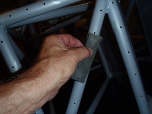
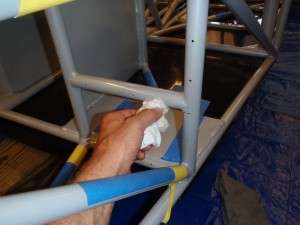
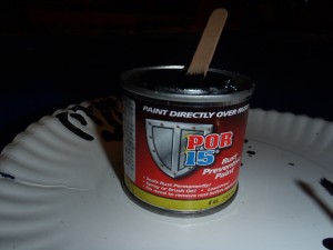
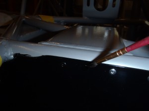
Now finally to apply tiger seal and rivet into position. See tool pic required. MNR supplies an excellent product called tiger seal to help to bond the floor boards to the chassis. MNR also supplied the required rivets for this job. So I scuffed up the chassis and frame with Scothbrite, cleaned applied the tiger seal and clecoed the floorboards into position and did the final riveting. I also used the tiger seal to seal any small air gaps that may exist to make and air tight seal between floor boards and engine compartment, as the floorboards function as a firewall and fume separation between engine compartment and driver. I finished up by applying some Por 15 paint to the rivet heads to seal and make a matching black, floor boards are installed and done. See picture.


