I was not too pleased with my last post regarding grouping the pictures toward the end of the post and will return to mixing the pictures within the commentary. Besides deconstructing the Miata, I am using these pages to prepare for writing the VortX miata assembly blog. So just bear with me as I experiment with this forum.
Now that the wiring harness is removed, we can finish removing the remaining donor parts, which is most of the drive-train all still connected to the PPF and front and rear sub-frames..With the body removed I have excellent access and this should make the rest of this deconstruction process go rather smoothly.
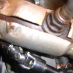
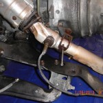
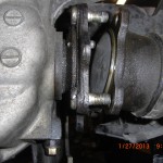
Since the down pipe still attached appears to be lower than the PPF and may possible contact the ground when the differential is removed from the PPF,I decide now would be a good time to remove the down pipe with the O2 sensor still attached to get it out of the way.Use a 12 mm socket to remove exhaust clamp bolt. Use 14 mm socket to remove down-pipe to exhaust header nuts.The nut closest to the block is difficult to remove, you will need to use a U-Joint swivel with 3 inch extension and with this set up I was able to remove, see pic,I would loosen this nut first. I intend to Turbo my VortX build and will need a custom down pipe. For those of you building a normally aspirated engine I would put this in the maybe required pile of parts. I will clarify if needed in a later post.
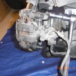
Next I turned my attention to the rear. I should mention, make sure you have the rear sub-frame securely supported on jack stands and the front wheels chocked to prevent rolling off the stands. With rear wheels removed I decide to remove both rear brake caliper assembles. Use 14 mm socket to remove two retaining bolts per caliper. But bolts and calipers into the donor pile.Slide off brake rotors put in donor pile.
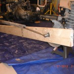
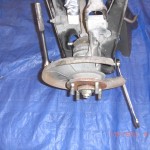
Now I decide the rear hubs, hub carriers(uprights) and CV axle drive shifts are my focus. To remove the rear hubs refer to page 9:21 in the manual. I first set up my magnetic base and dial indicator to check wheel bearing play. Mine is about 1/10,000 so excellent.As I read instruction 20 on page 9:22 Then I realize I have one of those OOPS moments. I started this deconstruction process by asking myself ,”where do I start?”. Well I think I now have the answer to this question. I no longer have a hand brake or any hydraulic brake system to prevent the hubs and axles from turning when the axle nut that is retained by 216 ft lb of torque is loosened. So if you are following along and have not removed your donor cars brakes, I would for a first step check your front and rear hub run-out per the manual and I would use the still operable brake system and break loose the the hub nuts, drive-shaft to differential and axle CV joint to differential bolts. Do not remove, just break them loose. But since I no longer have this option, I had to make my own Special Service Tool(SST) to remove the axle nuts and drive shaft bolts. This was done for the cost of a 2x6x8. I cut the 2×6 down to about 7 feet. Using a blue magic marker I applied the marker to the ends of the hub bolts and with one end of the 2×6 just behind the front tire I placed the opposite end of the 2×6 up to the still wet hub bolt ends to transfer the blue marker ink onto the 2×6.I drilled these holes with a drill bit, sorry I did not record the size but just pick one just slightly larger than the hub bolts. Now I applied the blue marker to the end of the threads where the hub nut is attached. I used a small 3/16″ drill bit to drill a pilot hole into the center of this larger blue mark. I then used a 2″ hole saw and using the pilot hole as my guide I sawed from both sides of the 2×6 to center to remove the round wood waste. I now would recommend a slightly larger 2 1/8″ hole saw if available but the 2″ got the job done. So what I am going to do is place the drilled holes over the wheel hub bolts to make a long lever to press against the floor as I loosed the hub nuts. To remove the drivers side hub nut , I place one end of the 2×6 is just behind front tire. This will prevent rotation to left as we loosen. I am able to use the large 2 inch center hole to access the hub bolt with the socket. Now with this SST in position I am ready to proceed following the instructions on page 9-22 in the manual to remove hub. But at this time before removing the hub nut, and with the SST in position take some time and break lose the nuts retaining the inner CV joints to differential connection joint for both axles. Use a 14 mm wrench or 14 mm 3/8″ drive socket as 1/2″ drive will not fit to break loose these bolts. Then using a 14mm 3/8″ drive socket brake loose and if you want you can remove the 4 bolts retaining the rear drive shaft yoke to the differential mounting flange. We really do not need to mark drive-shaft position to differential as we will be using a custom or modified shaft. The reasoning you want to do loosen the axle bolts prior to removing both rear Hubs as after you have the hubs removed, you will not be able to use the 2×6 SST to prevent rotation of axles. OK now we can proceed to remove hubs and axles.
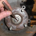
I did not have a 29 mm socket which is the correct size to remove the hub nuts, so I followed the advice in the manual and used a 1 1/8″ socket size and it fit perfectly. Before you attempt to loosen the hub nut make sure you use a drift punch to straighten out the locking staked portion of the nut. It is on tight enough without forgetting to this step.
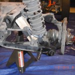
With 1 1/8″ socket over nut and using my 1/2″ breaker bar with about a 3ft extension of black pipe positioned to gain leverage, I placed one foot on the SST and pushed down on the breaker bar until it broke loose. Actually it broke loose rather easily. So after doing it this way using the 2×6 as a SST, this method is actually not a bad alternative. Next I used a 14 mm socket to remove the single bolt that connects the sping/damper unit to the lower control arm.
Repeat to other side and place the spring units into the e-bay pile.Use a 14 mm socket and 14 mm wrench remove upper upright bolt.
Use a 17 mm socket & 21 mm wrench or socket and remove the long lower upright pivot bolt.
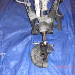
Apply some WD 40 to aid removal of this long bolt. Now we are ready to remove the unrestrained upright hub unit from the axle splines. One side of my Donner the hub unit separated from the splines with no effort at all, for the other side I followed the advice of the manual by placing the hub nut over the axle and tapping with hammer and pulling
simultaneously after a couple of rather easy taps the hub came free from the splines. Remove upright and place upright and bolts in the required donor pile. Repeat for other side. I did mark the location of the axle shafts to the differential mounting flange as manual suggest. Using 14 mm socket remove the all ready loosed axle bolts , remove axle,label and put into the donor pile. Repeat for other side to remove axle.We now
have both rear calipers and mount assemblies, 2rear brake rotors, 2 rear uprights and hub assemblies, 2 rear CV joint half shat axles and all associated hardware all labeled in the donor pile.And the down pipe with O2 sensor in the “maybe pile”.
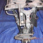
I next intended to go ahead and remove the rear differential as this is the last major donor part that is connected to the rear sub-frame.But I decide it may be best at this time and a good idea while the car is securely supported at rear by the rear sub-frame( as the ppf is directly connected to the differential) to remove the front calipers, rotors and to break loose the front hub nuts as we can use the mass of the engine to work against to help remove the tightly torqued hub nuts.


