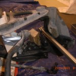
Since last post I gave a thought , that maybe the next step should be to remove the engine from the sub-frame, but decide I may need this mass to resist torque of removing ball joint castle nuts. It turns out this was the right decision.
First use a 17mm socket, which seems to be the go to socket for the suspension, and remove the lower bolt retaining the strut spring unit to the lower control arm. Repeat for the other side and put the strut spring units in the e-bay pile.
Next up I did remove the wheels to access the ball joint and tie rod cotter keyed castle retaining nuts. You need to support the weight of the engine unit with the wheels off. Use jack stands or suitable support. As you know I do have the engine crane in position with the legs under the sub-frame. I place a couple of pieces of 2×4 material on the top surface of the engine crane and used the legs of the engine crane for supports, worked.But it may be possible to break loose the castle nuts with the wheels on, if so do so. First remove the 6 cotter pins from upper and lower control arms and the two tie rod ball joints. Use 17 mm socket to break loose the tie rod and the upper ball joint castle nut, not need to completely remove.
You will need a 21 mm socket to remove the lower ball joint retaining nut.
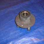
After the castle nuts are loosened go ahead and remove the wheels and tires if you have not done so by now. Slide brake rotors free of hubs, and use the 29 mm or the more common 1-1/8″ socket to remove the hut retaining nut(which we have previously loosened). After the nut is completely removed the hub is now free and and be removed from the stub axle see page 9:21 in the manual. Repeat for other side and place brake disk along with calipers, hubs and retaining bolts and nuts in the required donor pile parts.
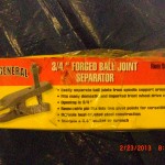
Now we need to separate two tie rod ball joints and 2 upper and 2 lower control arm ball joints. Refer to 8:16 in the manual. As you read the manual you will find out they were not able to purchase a separator tool that would fit. They use a wedge chisel separator and big hammer and brute force. My ball joints were very, very tight and I would not encourage anyone to remove the joint is this manner. I was able to buy an inexpensive 3/4″ ball joint separator tool for about $20.00 from Harbor freight. Their tool item number for this separator is 99849. You need this tool. It fit perfectly and made what could be a very tough job almost easy as I was able to separate all the joints and remove uprights in about 2 hours and that includes my time to make notes for this blog.
I did one side at the time. I started by removing the steering rack tie rod ball joint first. A couple of suggestions for using this tool I loosed all the castle nuts until they were about flush with the head of the threaded part of the tie rod. You will soon find out when the tie rod breaks free of the Morse taper that it can be rather explosive and I thought it a very good safety idea to leave the castle nut in place to contain this separation.Also as hint use some WD40.After tie rod is separated, remove castle nut completely and release tie rod from upright.
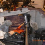
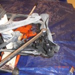
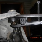
To left is the separator tool in position with the castle nut in place to contain separating parts.Make sure tool is in proper position, It is OK to tap the forked end into place with a hammer to get proper insertion.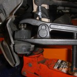
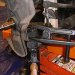 For the larger lower joint you will need to adjust the separator tool to use the upper ( you want to increase the spread) pivot pin holes locations.You can see the different pin position in pictures.
Some suggestions on use of tool. I did apply WD 40 to taper joint area prior to positioning of tool on the ball joint. You will use your ratchet or breaker bar to turn the screw on the separator tool.
After several turns and the breaker bar is providing quite a bit of resistance to turn screw, this is when you are thinking to yourself, I can not believe it has not broke loose or something is going to break, Well this is the time to get a good heavy hammer and give the ball joint a swat with the hammer. Using this method two of my joints immediately separated. For the other I would tighten the screw anther half turn , then give it a few swats and then another ½ turn and with the next hammer blow it separated. Only one of my joint separated without using the hammer technique.
It always is amazing to me just how much retention force a morse style taper can provide with out any bolt applying pressure. Many of the lower HP aviation engines attach the prop flange to the crank with a similar taper. I once needed 20 tons of force to remove a prop flange!. So it was expecting it would and should take some force to separate the joints from the upright.
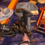
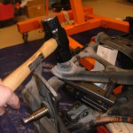 So after all your joints are broke loose, completely remove all the castel nuts and remove the upper ball joint first from the upright and then lower, the upright is now free.
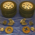
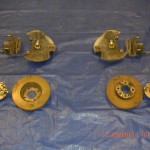
Put the upright in the required donor pile parts and repeat for the other side.Here is a group portrait of the front end donor parts including the wheels.
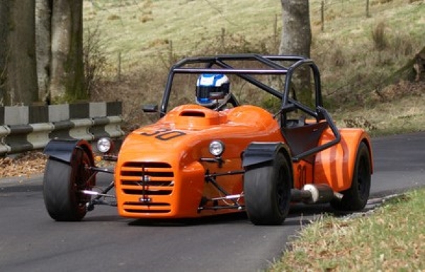
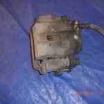
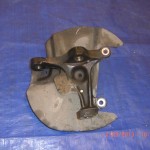
Below are a couple of pics of the donor parts before recondioning. Hopefully they clean up an be VortX worthy.
Well this concludes todays post. Basically all we have left to dissasemble is to remove the engine from the subframe motor mounts. Just 2 bolts left.
Stay tuned.
