
It is too long since last post. I really need to make it a rule to write the post within 48 hours of doing the job task. This is easier for my memory.
My nephew was in town from TX and 48 hours turned into a couple of weeks. So here goes. At my last post we only had to remove the engine from the sub frame or should I say the sub frame from the engine. So that is what I did next.
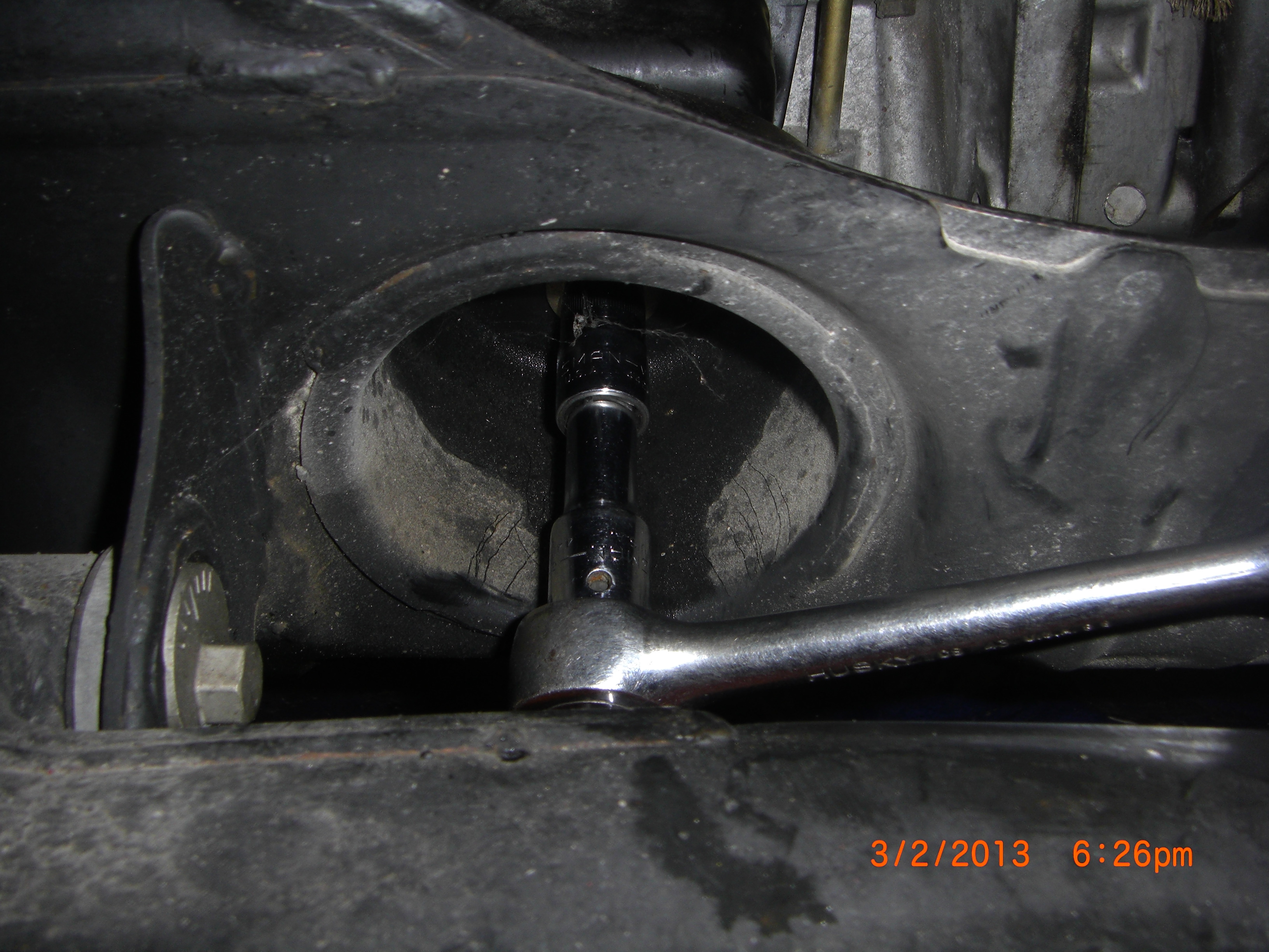
Use a 14 mm socket with short extension to reach the engine mount retaining bolt through the recessed round bulkhead access located on the underside of the front sub-frame. See pic.
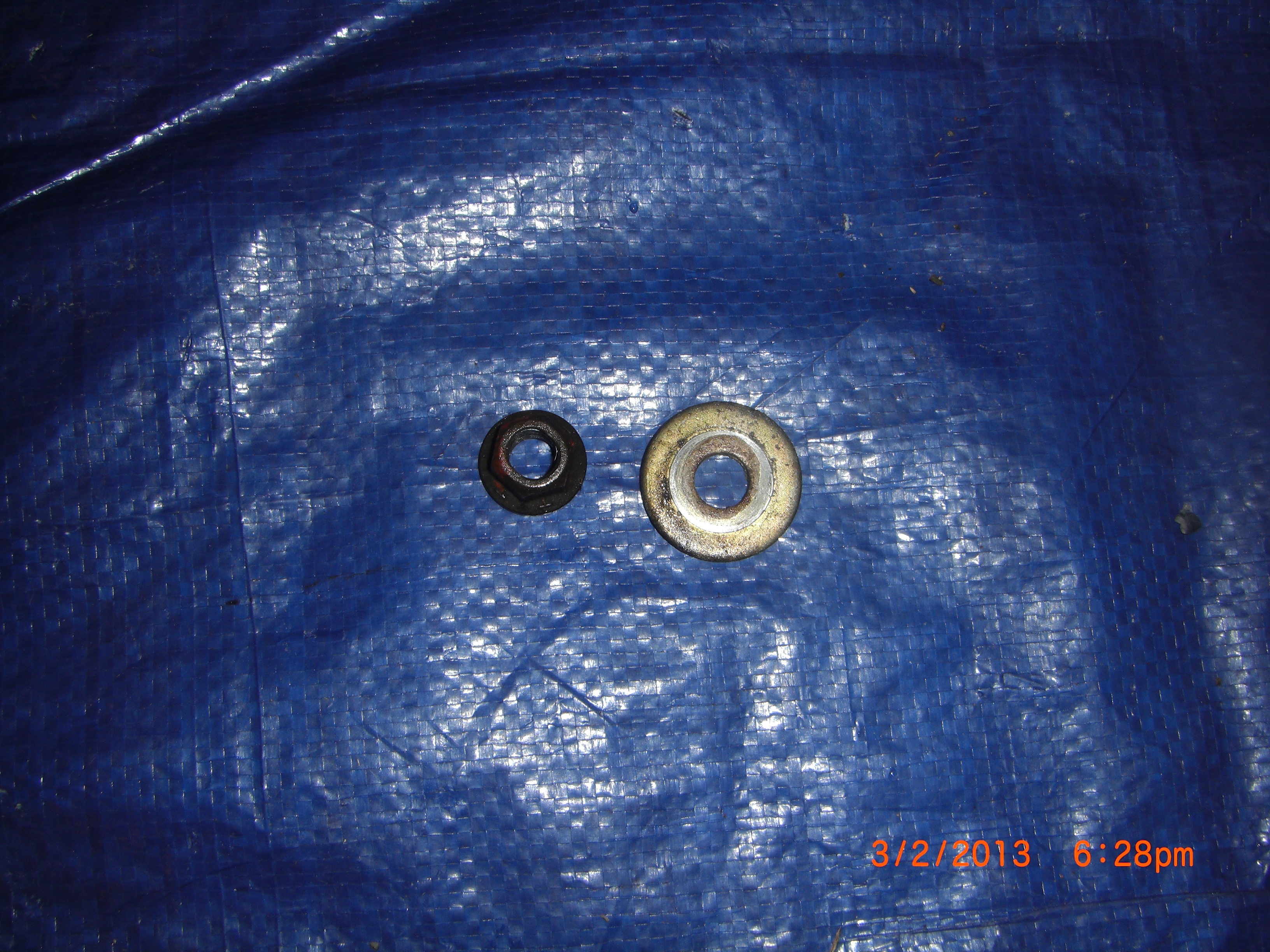
Repeat for other engine mount. Remove nut and large flat washer. See pic.
After bolts are free I used the engine crane and lifted the engine free of the front sub-frame. I little wiggling of the sub frame was needed to assist. This engine mount is broken, See pic.

The rubber part should have stayed with the fabricated bracket still attached to the engine. I have ordered MazdaSpeed competition engine mounts for the VortX build. I am creating a growing list of list of all the Mazda and aftermarket part numbers used in refurbishing and building the VortX, I will publish this list for builder’s reference.
See pic of metal brackets that the new MazdaSpeed Competition will cradle.
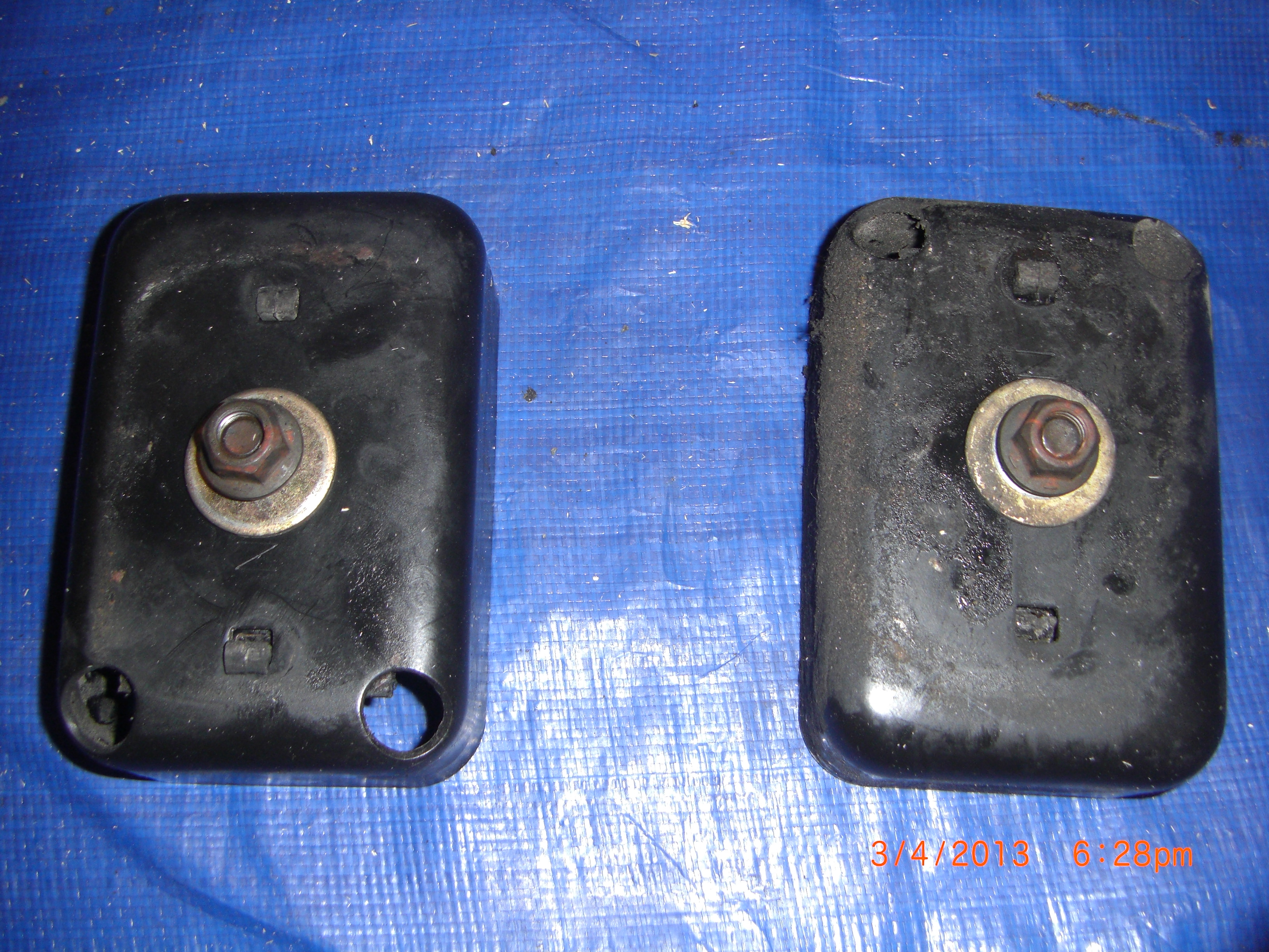
Put these metal brackets and hardware in the donor parts pile. This was bout a 10 minute or less job.
With the engine suspended above the front sub-frame,
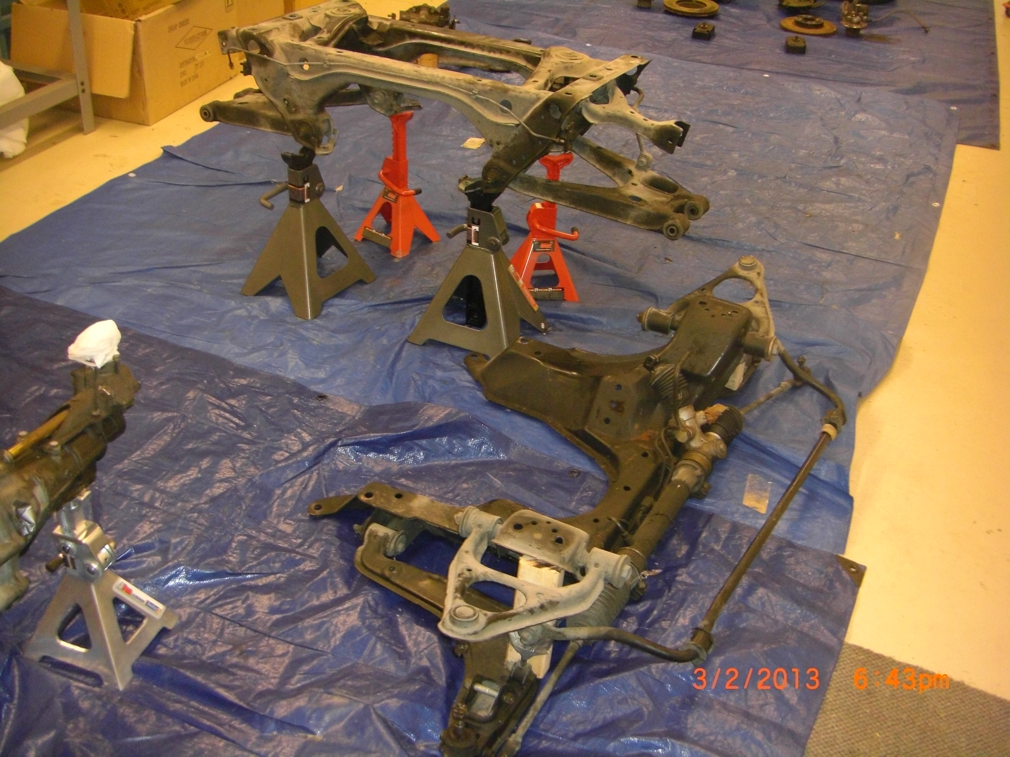

I picked up the sub-frame and moved it out of the way. But now what am I going to do with the heavy engine? I really did not give this enough for forethought and I do want to be able to move this around the shop. After looking the engine over I noticed a pair of vertical holes you will find them if you look behind alternator and just below and in front of oil filter and similarly on the opposite side of the block. This gave me an idea for a very simple and cheap way to support and move the engine around the shop. I found some rusty 2x2x1/8 angle in my garden shed and a piece of 2×4 wood framing I will use to make an engine support. I cut the angle stock into two pieces 10-1/2” long. I then drilled two holes in one angle face ( where I will bolt to the engine block) I located the top hole 1 1/8” (STD steel gage) from the back of 90 degree bend and the same 1 1/8” from the end of the 10-1/2” angle. I then located the second hole 1 -13/16” below the first hole location. I drilled the holes using a 7/16” drill. These two holes will bolt the angle to the engine block.
Now using the same 1 1/8” gage I drilled a 3/8” diameter hole 1 ¼” up from the other end of the 2 and ½”angle and on the opposite face of angle. This hole will bolt to the 26 inch 2×4 with 5/16” x 2” bolts. Cut the 2×4 to a length of 26 inches.
Make another angle to be a mirror image of the first.
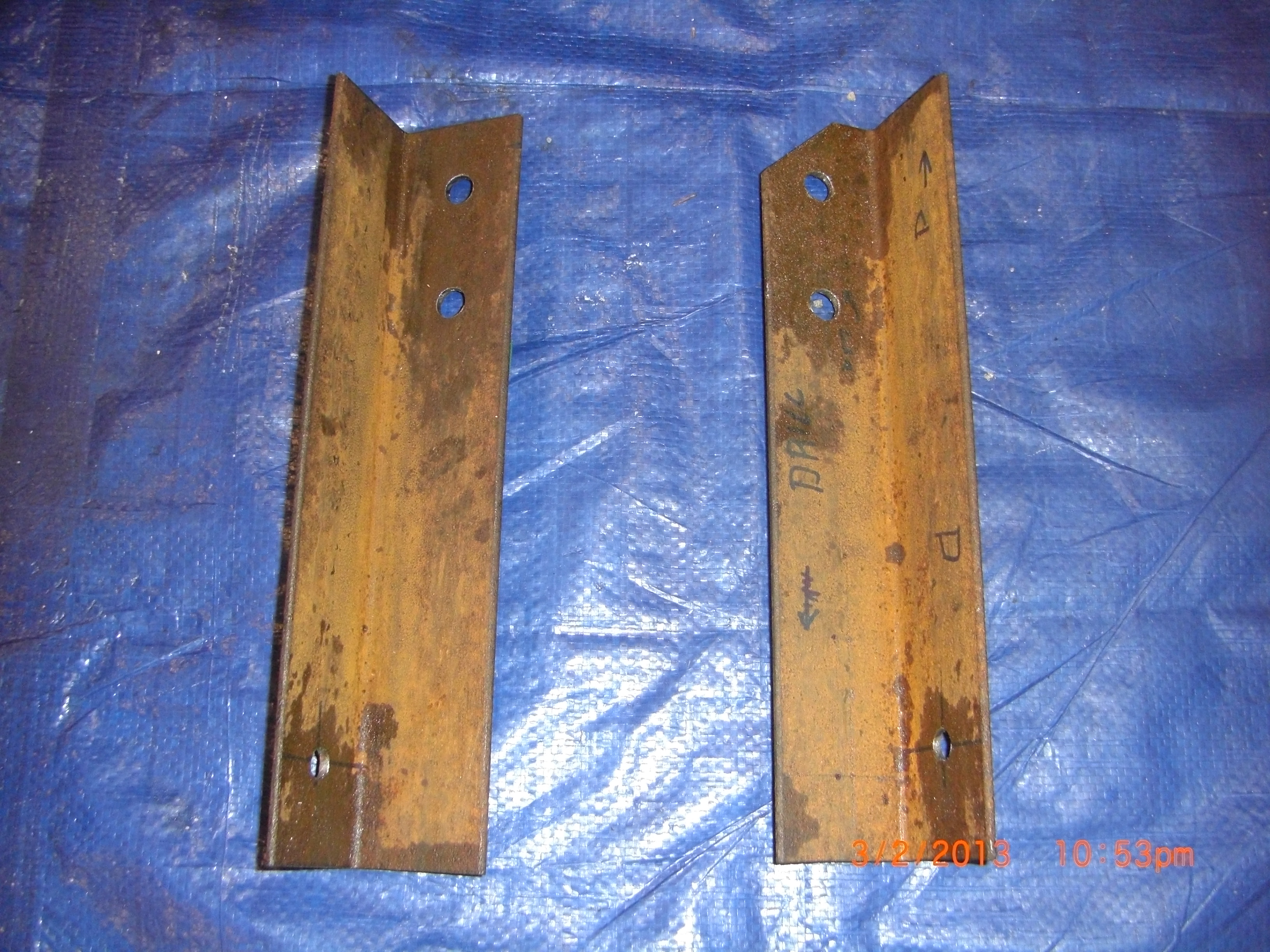
I trial fit the angles to the block and I had to cut a 45 degree corner off of one angle face to clear the oil filter. See pics of the rusty angles with drilled holes. I decided I would paint the angles prior to use so I will finish this support frame tomorrow. So at this time I used a 14mm socket to remove the bolts that retain the steering rack to the sub-frame. This is not a necessary step and if you want you can leave attached to the front sub-frame, but since I am waiting for paint to dry, now is a good time to remove the rack. The VortX comes with a brand new quick ratio rack, so I am only removing the donor car rack to put in the e-bay for sale pile.
I painted the rusty angles with Rust-oleum rusty metal primer, this is my favorite paint for any ferrous metal refurbishment projects and I would like to make some commentary about this primer.
I have used this primer for years and I am most impressed on how it prevents return of rust. I first used this primer many years ago to paint a pipe used for a mail box support. My only preparation was to wire brush the major rust scaling off. I did not fully remove the existing rust and painted over the remaining rust with Rust-oleum rusty metal primer, I did not bother to put a top coat on. I fully expected it to return to the fully rusted condition in very short time. Long story short, this pipe looked as good as the day I painted it several years later! I have since used it many times and always with the same outstanding results, it really does the job of preventing return of rust. So for this reason I intend to use this paint as my go to primer for any parts that I recondition by stripping, bead blast etc. prior to finish painting.
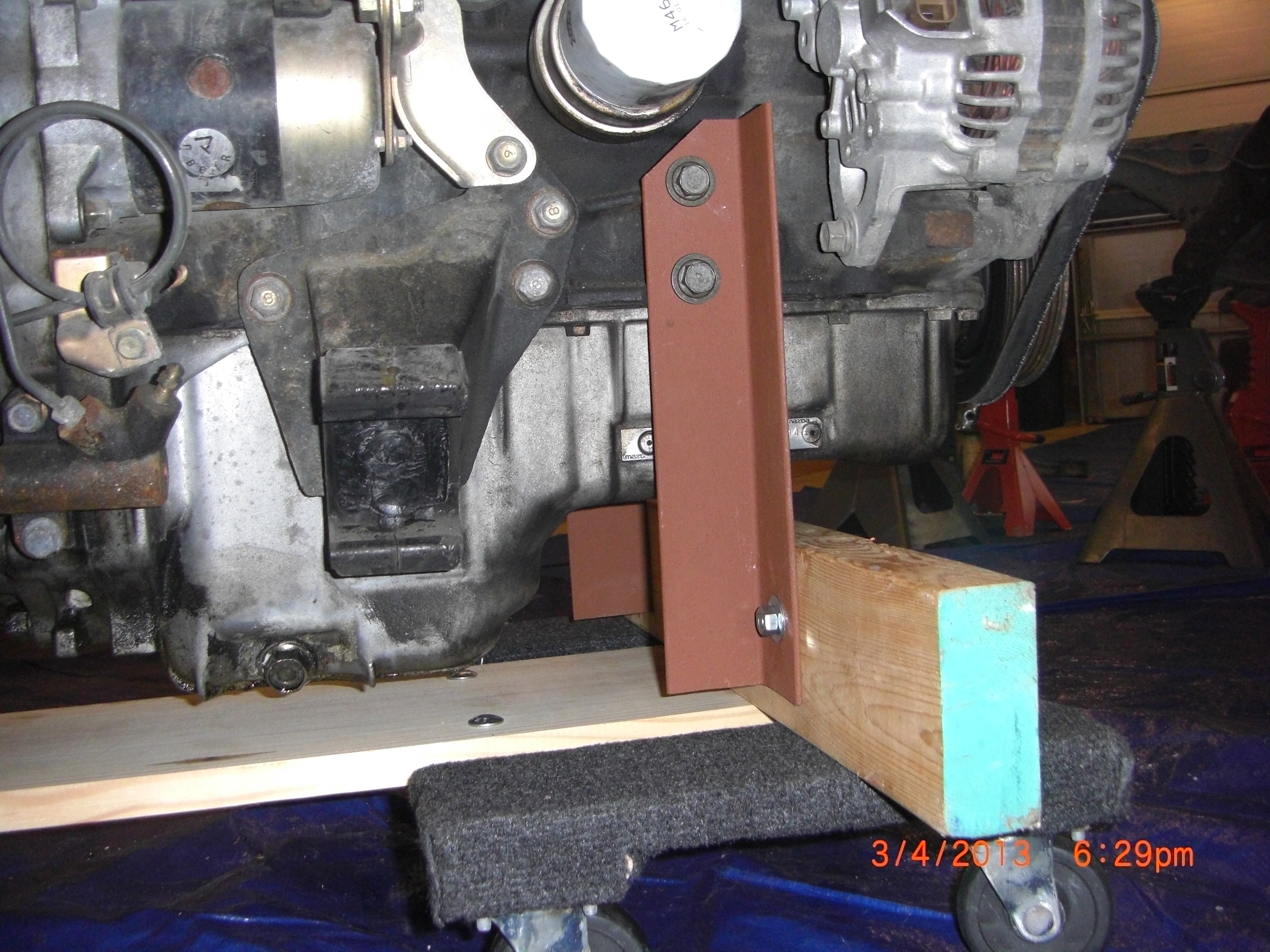
For example I intend to paint the uprights and the differential and front and rear hubs. The differential and hubs will be subjected to some moderated but not high temps. Will this paint hold up? So I decided I would do an experiment to find out. I used a 3 inch piece of the same angle used for the engine stand and painted one side of the angle with this primer and the other side with VHT engine enamel. I put the piece in the oven at a temp I estimate the max for these parts of 200 Deg F for several hours. Both test samples held up great. So I kept turning up the heat and after 12 hours at 450 Degrees F, I removed the samples and using a primitive and unscientific test of a scraping a knife along the painted surfaces, the Rustoleum sample held fast and surprisingly the VHT paint was soft and some scraped off! So while I do not intent to use this primer for engine or brake calipers, I feel assured this is good primer paint for all but high heat applications. After the paint dries I was able to find 4 bolts from my coffee can of bolts I removed during disassembly to fit the holes in the engine block to mount my now nicely painted and dry angles to. After bolting these angles in place, see pic


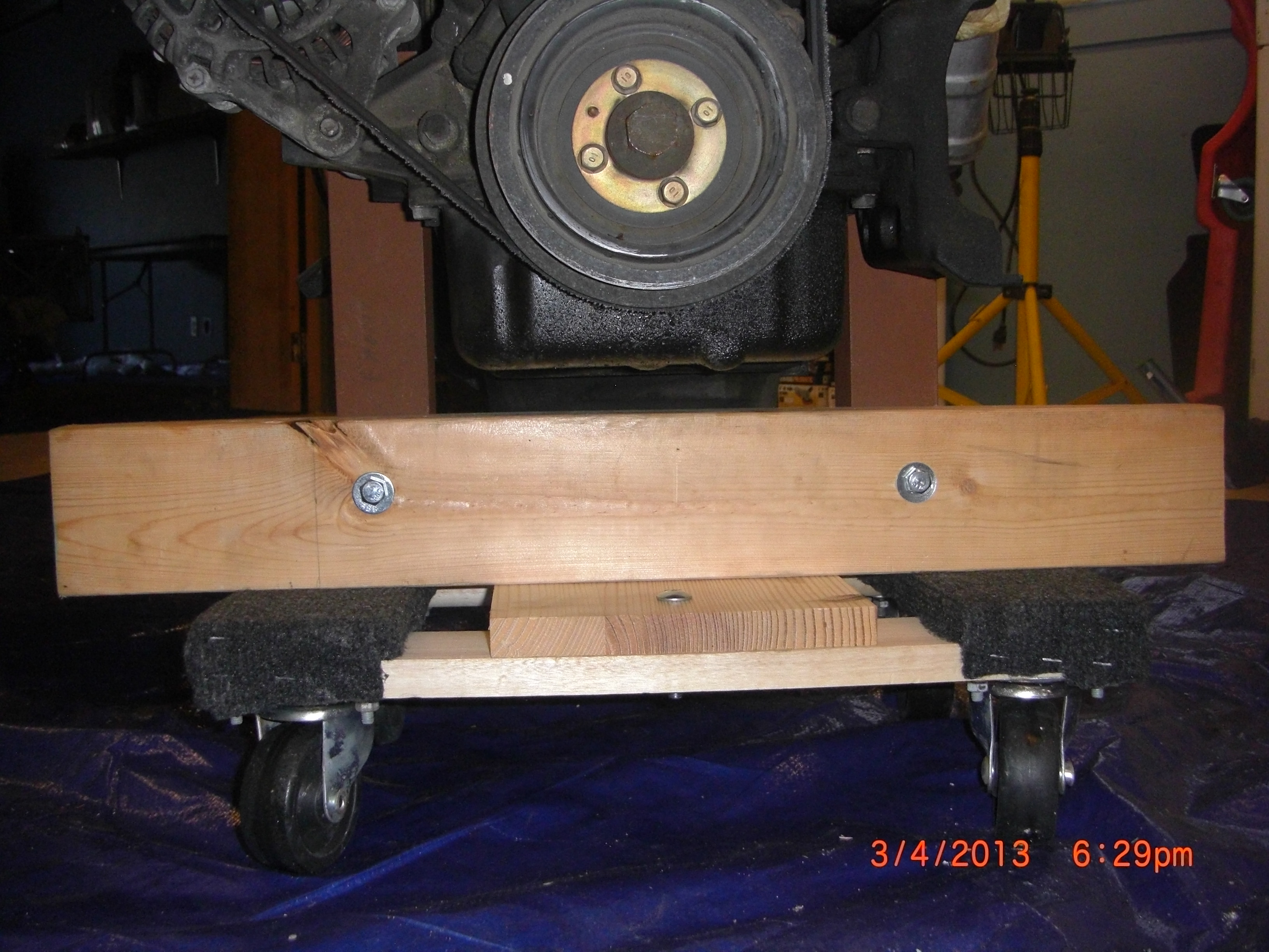
I clamped the 2×4 to the front face of the angles. I made sure the bottom of the 2×4 was about ½” below the angles so the angles would not scrap the floor surface. I marked the holes and drilled using a 3/8” drill. Then I bolted the drilled 2×4 to the face of the 2×2 angles using 5/16” bolts, see pic.
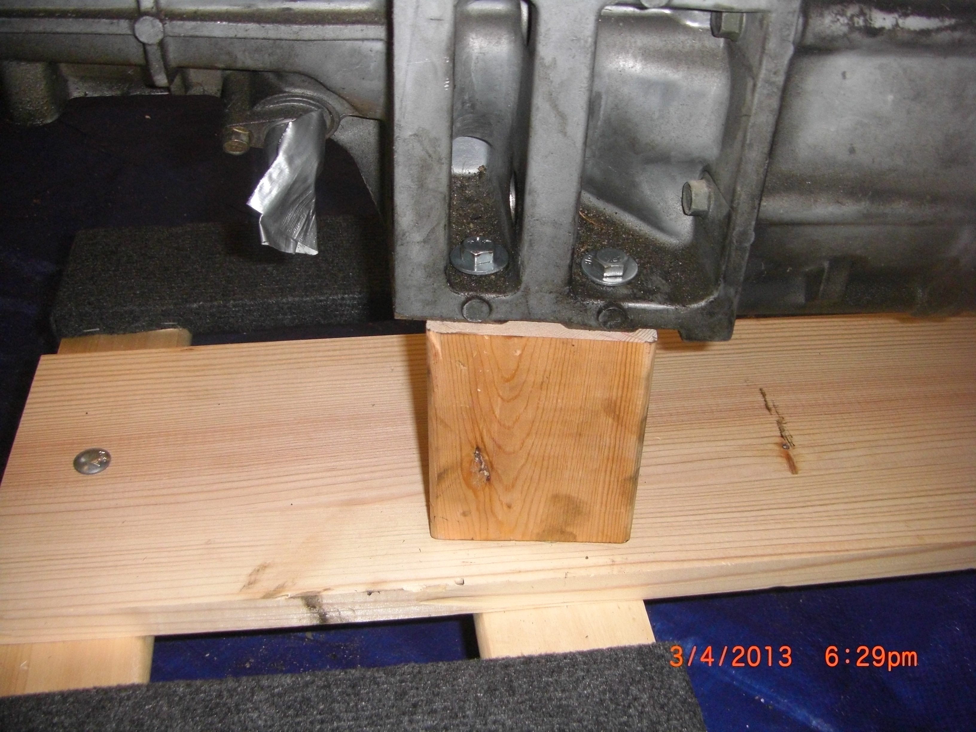
I then decided I wanted to keep the transmission off the floor and simply cut a piece of 2×4 to a length of approx 4-3/4” and positioned below the rear transmission mounting and marked and drilled ¼” pilot holes. Then using 2 ½’ x 3/8” hex headed wood screws I bolted the wood to the trans mount. Built as described the bottom of the 1.8L engines oil pan is about 1” above the floor surface. Adjust your angle lengths to suit if more clearance is desired.
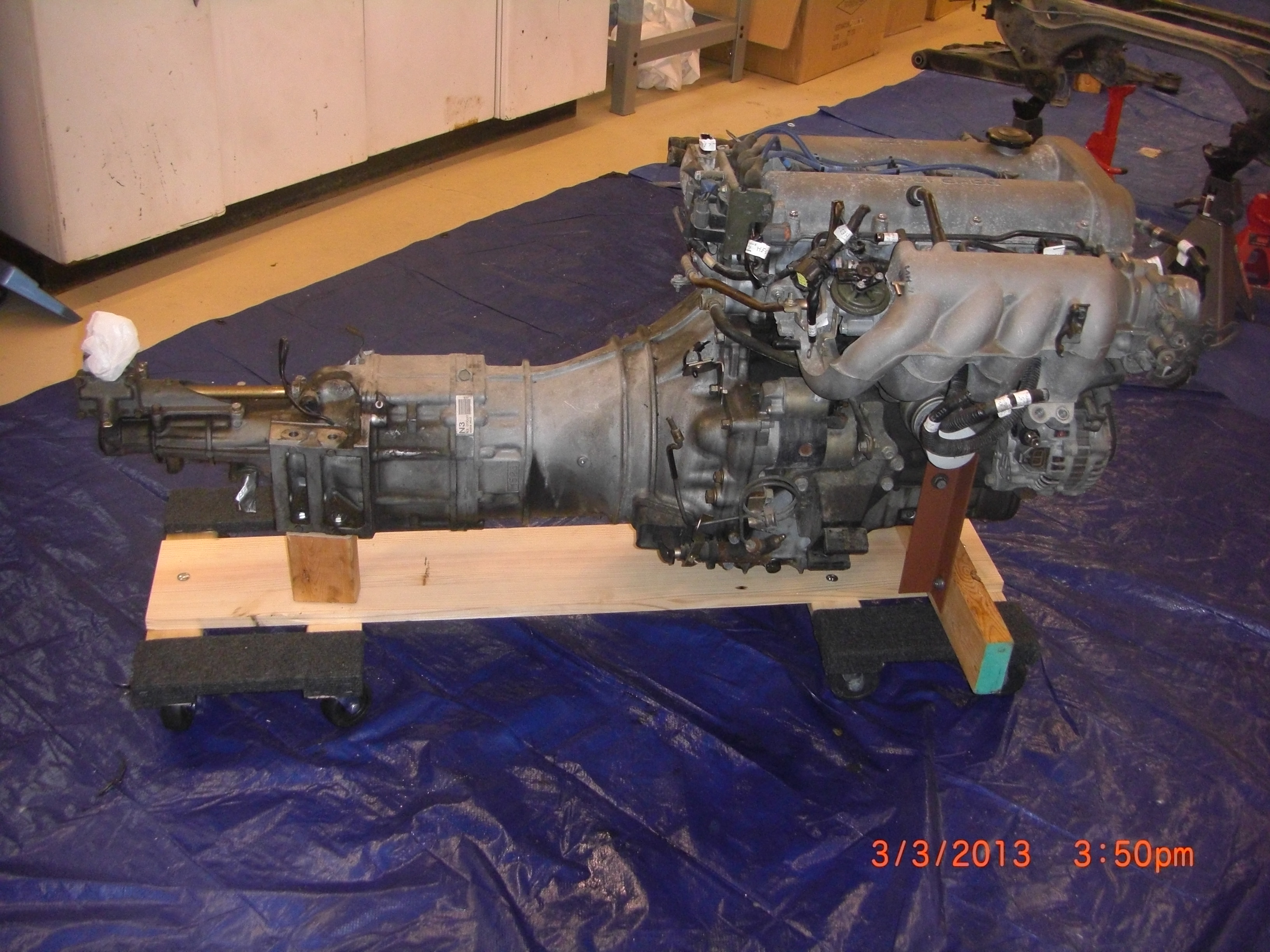
Now that the engine trans unit is safely supported I still have the problem of moving it around the shop. My original plan was to buy some castors and attach directly to the stand I made, but then I read the Harbor freight flyer and seeing 1000 Lb capacity 11 ½ x17 ½ furniture movers on sale for about $10.00 each I had another and very simple plan.
I bought two of these and stopped at Lowe’s bought a precut 1” x 8”x48” piece of wood used for making stairway runners. I also picked up six 5/16” x 2” lag bolts. I simply drilled three 3/8” holes in each dolly and bolted the stair runner to it. Very simple and easy to make. I used the engine crane to lower engine onto this mobile “skateboard” platform. It works great and I can easily move around the shop and I am sure this “skate board” will find future use for other purposes. With the engine stand completed we have now concluded the deconstruction phase of this project and this will be the last post under the harvesting of donor parts topic heading, hence “last stand” post title.
I must admit I was not looking forward to the disassembly process. But it went much easier than I thought and I actually enjoyed it and this was an excellent way to learn details about the Miata that will serve me during the build. I now have a good assortment of quality parts to sell that should allow me to recover most of the initial expense of the donor purchase. I invested a total of less than 40 hours in disassembling the donor and half as much writing the blog. In retrospect using the Miata as a single donor to build the VortX is to me is a “no brainer” and I highly recommend to potential builders to buy a Miata( go to Co-Part to find your donor Car) and do the disassembly yourself. You will learn a lot and this is a very cost effective way to go.
Now I must say I am very much looking forward to the next phase of this project.
What comes next? Well before we can get into the build I will first need to refurbish some of donor parts for the build. So the topic heading for my next post will be Refurbishment of the donor parts. Will be posting soon.